Frequency Shifting: Difference between revisions
No edit summary |
|||
| (24 intermediate revisions by the same user not shown) | |||
| Line 6: | Line 6: | ||
Multiplying a signal by a complex sinusoid with frequency f Hz will translate or shift the center frequency of the signal by f Hz. For example, to frequency shift a signal by 1 MHz a complex signal must be generated with frequency 1 MHz, and then multiplied against the desired signal in order to frequency shift it. | Multiplying a signal by a complex sinusoid with frequency f Hz will translate or shift the center frequency of the signal by f Hz. For example, to frequency shift a signal by 1 MHz a complex signal must be generated with frequency 1 MHz, and then multiplied against the desired signal in order to frequency shift it. | ||
==Build Example Signal== | ==Build Example Signal== | ||
| Line 16: | Line 15: | ||
* QT GUI Frequency Sink | * QT GUI Frequency Sink | ||
[[File:frequency_shifting_flowgraph.png]] | |||
The flowgraph is an offline simulation to the choice of sampling rate is somewhat arbitrary, but a sample rate of 10 MHz is chosen to realistic number. | |||
[[File:Frequency_shifting_samp_rate_properties.png]] | |||
The low-pass filter properties are updated to define the cutoff frequency and transition width: | |||
* Cutoff Freq: ''samp_rate/8'' | |||
* Transition Width: ''samp_rate/16'' | |||
[[File:frequency_shifting_low_pass_properties.png]] | |||
Running the flowgraph then displays a simulated signal: | |||
[[File:frequency_shifting_example_signal.png]] | |||
The signal has not been shifted yet and therefore has a center frequency of 0 Hz. | |||
==Create Complex Sinusoid== | |||
A complex sinusoid is added to the flowgraph which will be used later to perform the frequency shifting. Add the following blocks and connect them to the flowgraph: | |||
* Variable'' | |||
* Signal Source | |||
[[File:frequency_shifting_flowgraph_sinusoid.png]] | |||
The flowgraph is an offline simulation to the choice of sampling rate is somewhat arbitrary, but a sample rate of 10 MHz is chosen to be a realistic number. | |||
[[File:Frequency_shifting_new_center_frequency_properties.png]] | |||
The variable ''new_center_frequency'' is then used for the frequency in the signal source block: | |||
[[File:Frequency_shifting_signal_source_properties.png]] | |||
Increase the number of ports on the '''QT GUI Frequency Sink''': | |||
[[File:Frequency_shifting_frequency_sink_properties.png]] | |||
Now run the flowgraph: | |||
[[File:Frequency_shifting_run_flowgraph.png]] | |||
You can now see the new complex sinusoid that has been created and displayed in '''<span style="color:red">red</span>''': | |||
[[File:Frequency_shifting_signal_and_complex_sinusoid.png]] | |||
The frequency shifting process will apply the blue signal against the '''<span style="color:red">red</span>''' complex sinusoid, centering it at 1 MHz. | |||
==Perform Frequency Shifting== | |||
Add the '''Multiply''' block into the flowgraph and connect it such that it accepts the outputs from '''Low Pass Filter''' and '''Signal Source''': | |||
[[File:frequency_shifting_flowgraph_multiply.png]] | |||
[[File: | |||
The multiply block now performs the frequency shifting, moving the center frequency of the signal up to 1 MHz. Running the flowgraph shows the input signal centered at 0 Hz and the frequency shifted version at 1 MHz: | |||
[[File:frequency_shifting_centered_1MHz.png]] | |||
The frequency shifted value can be positive or negative. Update the ''new_center_frequency'' variable to be -3 MHz: | |||
[[File:Frequency_shifting_update_new_center_frequency.png]] | |||
Running the flowgraph now shows the signal centered at -3 MHz: | |||
[[File:frequency_shifting_neg_3MHz.png]] | |||
A '''QT GUI Range''' block can be used to change the center frequency in real time. Right click on the ''new_center_frequency'' and select ''Disable'': | |||
[[File:Frequency_shifting_disable_variable_block.png]] | |||
The block will now be grayed out. | |||
Add a '''QT GUI Range''' block to the flowgraph: | |||
[[File:Frequency_shifting_qt_gui_range_block.png]] | |||
Open the QT GUI Range block and update the following properties: | |||
* ID: ''new_center_frequency'' | |||
* Default Value: ''0'' | |||
* Start: ''-samp_rate/2'' | |||
* Stop: ''samp_rate/2'' | |||
[[File:Frequency_shifting_qt_gui_range_properties.png]] | |||
Save the properties and run the flowgraph. The QT pop up window will now display a slider bar at the top which can be clicked and slid around to change the frequency and therefore move the frequency shifted signal. The text box can also be modified to set a specific center frequency: | |||
[[File:Frequency_shifting_slider_bar.png]] | |||
Revision as of 23:02, 5 April 2024
This tutorial describes how to perform frequency shifting, causing the frequency of a signal to change.
Frequency Shifting
Frequency shifting is the process of changing the position of a signal within the frequency domain. Equivalently, it can be stated that frequency shifting is the process of changing the center frequency of a signal. Frequency shifted can be implemented many different ways, although this tutorial will focus on the simple method of multiplication by a complex sinusoid.
Multiplying a signal by a complex sinusoid with frequency f Hz will translate or shift the center frequency of the signal by f Hz. For example, to frequency shift a signal by 1 MHz a complex signal must be generated with frequency 1 MHz, and then multiplied against the desired signal in order to frequency shift it.
Build Example Signal
First an example signal needs to be built. A simple signal of filtered noise is created. Drag in the following blocks and connect them:
- Noise Source
- Throttle
- Low Pass Filter
- QT GUI Frequency Sink
The flowgraph is an offline simulation to the choice of sampling rate is somewhat arbitrary, but a sample rate of 10 MHz is chosen to realistic number.
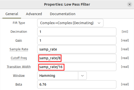
The low-pass filter properties are updated to define the cutoff frequency and transition width:
- Cutoff Freq: samp_rate/8
- Transition Width: samp_rate/16
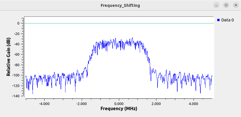
Running the flowgraph then displays a simulated signal:
The signal has not been shifted yet and therefore has a center frequency of 0 Hz.
Create Complex Sinusoid
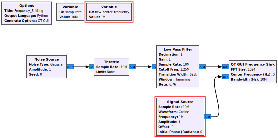
A complex sinusoid is added to the flowgraph which will be used later to perform the frequency shifting. Add the following blocks and connect them to the flowgraph:
- Variable
- Signal Source
The flowgraph is an offline simulation to the choice of sampling rate is somewhat arbitrary, but a sample rate of 10 MHz is chosen to be a realistic number.
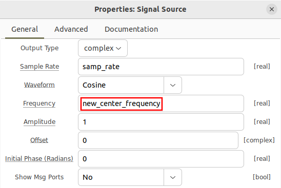
The variable new_center_frequency is then used for the frequency in the signal source block:
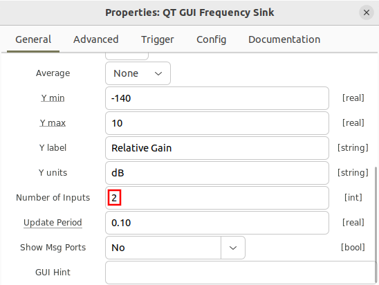
Increase the number of ports on the QT GUI Frequency Sink:
Now run the flowgraph:
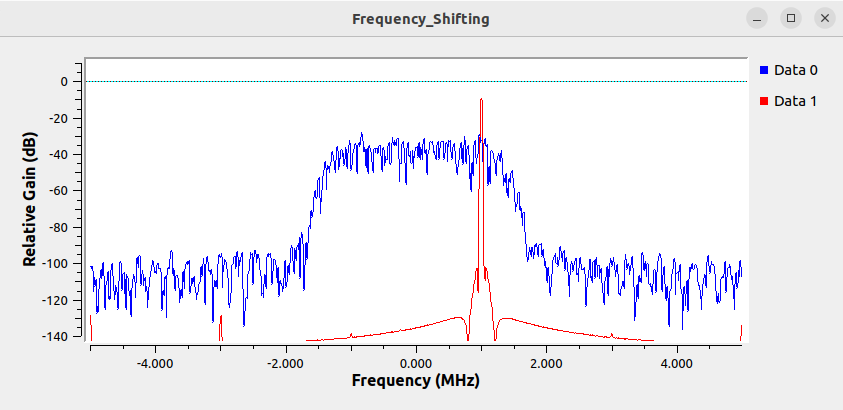
You can now see the new complex sinusoid that has been created and displayed in red:
The frequency shifting process will apply the blue signal against the red complex sinusoid, centering it at 1 MHz.
Perform Frequency Shifting
Add the Multiply block into the flowgraph and connect it such that it accepts the outputs from Low Pass Filter and Signal Source:
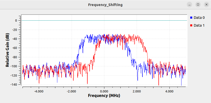
The multiply block now performs the frequency shifting, moving the center frequency of the signal up to 1 MHz. Running the flowgraph shows the input signal centered at 0 Hz and the frequency shifted version at 1 MHz:
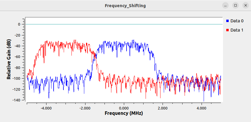
The frequency shifted value can be positive or negative. Update the new_center_frequency variable to be -3 MHz:
Running the flowgraph now shows the signal centered at -3 MHz:
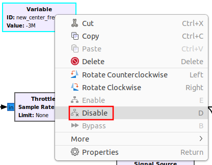
A QT GUI Range block can be used to change the center frequency in real time. Right click on the new_center_frequency and select Disable:
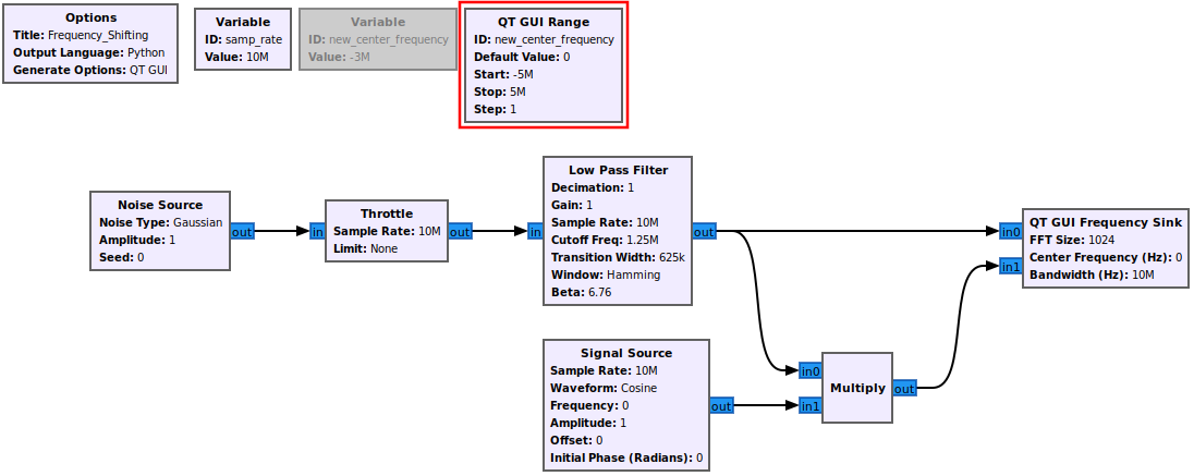
The block will now be grayed out.
Add a QT GUI Range block to the flowgraph:
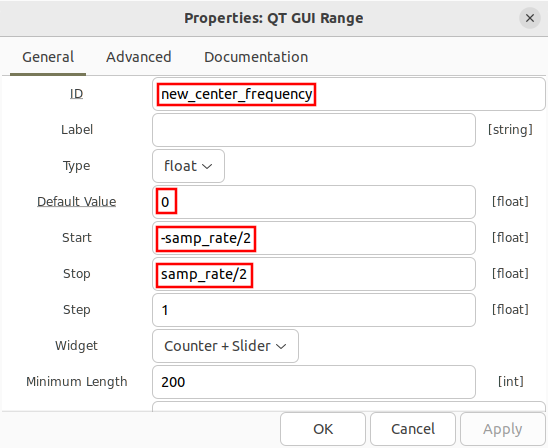
Open the QT GUI Range block and update the following properties:
- ID: new_center_frequency
- Default Value: 0
- Start: -samp_rate/2
- Stop: samp_rate/2
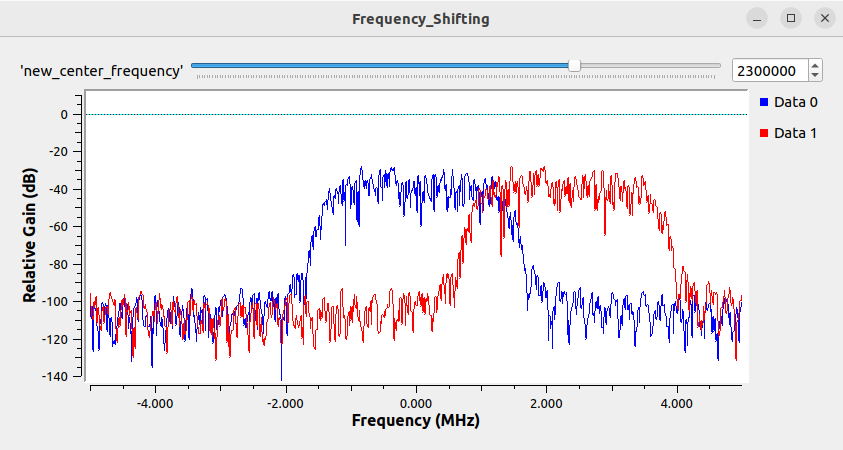
Save the properties and run the flowgraph. The QT pop up window will now display a slider bar at the top which can be clicked and slid around to change the frequency and therefore move the frequency shifted signal. The text box can also be modified to set a specific center frequency:


