Zynq: Difference between revisions
(Imported from Redmine) |
No edit summary |
||
| (4 intermediate revisions by the same user not shown) | |||
| Line 1: | Line 1: | ||
= OBSOLETE OBSOLETE OBSOLETE = | = OBSOLETE OBSOLETE OBSOLETE = | ||
These need reworking. If you are building for an embedded platform look at [ | These need reworking. If you are building for an embedded platform look at [[Embedded]] | ||
== FPGA Accelerators in GNU Radio with Xilinx's Zynq System on Chip == | == FPGA Accelerators in GNU Radio with Xilinx's Zynq System on Chip == | ||
| Line 14: | Line 14: | ||
== Warning: Instructions of out date == | == Warning: Instructions of out date == | ||
Development moves rapidly in Open Embedded and GNU Radio which unfortunately means this guide has become out of date and the instructions will likely fail. For now, please refer to our [ | Development moves rapidly in Open Embedded and GNU Radio which unfortunately means this guide has become out of date and the instructions will likely fail. For now, please refer to our [[Embedded]] and [[OpenEmbedded]] pages for the latest GNU Radio on Zynq information. This warning will be removed once the page has been updated. | ||
== Pre-built System Files and SDK == | == Pre-built System Files and SDK == | ||
| Line 135: | Line 135: | ||
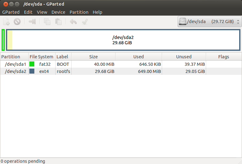
GParted is the easiest tool to prepare the SD card. Make two partitions: one named BOOT, fat32, size 40MB, marked as bootable and another named rootfs, ext4, rest of the free space. | GParted is the easiest tool to prepare the SD card. Make two partitions: one named BOOT, fat32, size 40MB, marked as bootable and another named rootfs, ext4, rest of the free space. | ||
[[File: | [[File:Gparted.png|Gparted.png]] | ||
For those not willing to use a GUI tool, | For those not willing to use a GUI tool, | ||
| Line 202: | Line 202: | ||
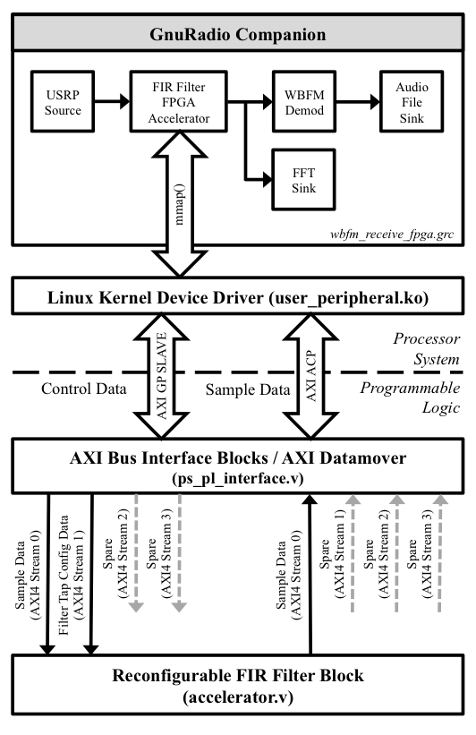
The figure below provides a high level overview of the FIR filter example components. | The figure below provides a high level overview of the FIR filter example components. | ||
[[File:FIR_Filter_Example_Block_Diagram.png|]] | [[File:FIR_Filter_Example_Block_Diagram.png|FIR_Filter_Example_Block_Diagram.png]] | ||
The example design can be separated into four sections: | The example design can be separated into four sections: | ||
| Line 251: | Line 251: | ||
The first image below shows a modified wideband FM radio receiver in GNU Radio Companion with the low pass filter replaced with the FIR Filter FPGA module. The second image shows the receiver tuned to local Boston FM radio station. The images were captured with GNU Radio Companion running on the Zynq hardware via ssh with X11 forwarding enabled. The flow graph can be found in gr-zynq/examples/wbfm_receive_fpga.grc. | The first image below shows a modified wideband FM radio receiver in GNU Radio Companion with the low pass filter replaced with the FIR Filter FPGA module. The second image shows the receiver tuned to local Boston FM radio station. The images were captured with GNU Radio Companion running on the Zynq hardware via ssh with X11 forwarding enabled. The flow graph can be found in gr-zynq/examples/wbfm_receive_fpga.grc. | ||
[[File:wbfm_receive_fpga.png|]] | [[File:wbfm_receive_fpga.png|wbfm_receive_fpga.png]] | ||
[[File:wbfm_receive_fpga_live.png|]] | [[File:wbfm_receive_fpga_live.png|wbfm_receive_fpga_live.png]] | ||
This is an image of the example gr-zynq/examples/fir_filter_fpga_tone_plus_noise_test.grc. The noise source provides a clear outline of the filter's frequency response magnitude. | This is an image of the example gr-zynq/examples/fir_filter_fpga_tone_plus_noise_test.grc. The noise source provides a clear outline of the filter's frequency response magnitude. | ||
[[File:fir_filter_fpga_tone_plus_noise_test.png|]] | [[File:fir_filter_fpga_tone_plus_noise_test.png|fir_filter_fpga_tone_plus_noise_test.png]] | ||
= Performance Analysis = | = Performance Analysis = | ||
| Line 265: | Line 265: | ||
The programs used to generate the data can be found in arm-fir-ccf/ and fpga-fir-cc/ in the gr-zynq/examples/performance_tests/ directory. | The programs used to generate the data can be found in arm-fir-ccf/ and fpga-fir-cc/ in the gr-zynq/examples/performance_tests/ directory. | ||
[[File:fpga_arm_performance.png|]] | [[File:fpga_arm_performance.png|fpga_arm_performance.png]] | ||
== Appendix A: Build Instructions for the FPGA Bit Stream, First Stage Boot Loader, and BOOT.BIN == | == Appendix A: Build Instructions for the FPGA Bit Stream, First Stage Boot Loader, and BOOT.BIN == | ||
| Line 291: | Line 291: | ||
uncheck checkbox "Include bitstream and BMM file" | uncheck checkbox "Include bitstream and BMM file" | ||
click "Export & Launch SDK"</pre> | click "Export & Launch SDK"</pre> | ||
[[File:xps_cropped.png|]] | [[File:xps_cropped.png|xps_cropped.png]] | ||
Once Xilinx's Eclipse based SDK program opens, you will be prompted to create a workspace folder. Another script in the instructions requires that the workspace folder be placed in a specific directory: zynq-acp/top/zedboard/build/zynq-ps/SDK/workspace. Make sure to prepend the appropriate path to your Zynq build directory, which is highlighted in the image below for added emphasis. | Once Xilinx's Eclipse based SDK program opens, you will be prompted to create a workspace folder. Another script in the instructions requires that the workspace folder be placed in a specific directory: zynq-acp/top/zedboard/build/zynq-ps/SDK/workspace. Make sure to prepend the appropriate path to your Zynq build directory, which is highlighted in the image below for added emphasis. | ||
[[File:sdk_workspace.png|]] | [[File:sdk_workspace.png|sdk_workspace.png]] | ||
After the program finishes loading: | After the program finishes loading: | ||
| Line 304: | Line 304: | ||
Select Zynq FSBL | Select Zynq FSBL | ||
Click Finish</pre> | Click Finish</pre> | ||
[[File:sdk_zynq_fsbl_1.png|]] | [[File:sdk_zynq_fsbl_1.png|sdk_zynq_fsbl_1.png]] | ||
[[File:sdk_zynq_fsbl_2.png|]] | [[File:sdk_zynq_fsbl_2.png|sdk_zynq_fsbl_2.png]] | ||
After Xilinx SDK finishes compiling zynq_fsbl.elf, which is needed in the next step to create boot.bin, both programs EDK and XPS are no longer needed and can be closed. | After Xilinx SDK finishes compiling zynq_fsbl.elf, which is needed in the next step to create boot.bin, both programs EDK and XPS are no longer needed and can be closed. | ||
Latest revision as of 14:23, 13 March 2017
OBSOLETE OBSOLETE OBSOLETE
These need reworking. If you are building for an embedded platform look at Embedded
FPGA Accelerators in GNU Radio with Xilinx's Zynq System on Chip
Jonathon Pendlum (jon.pendlum@gmail.com), GSoC 2013
Moritz Fischer (moritz.fischer@ettus.com)
Many signal processing blocks in GNU Radio exhibit parallelism and can be efficiently mapped to the architecture of a Field Programmable Gate Array (FPGA). Recently, FPGA vendor Xilinx released the Zynq, a System-on-Chip (SoC) that tightly couples programmable logic with a dual core Cortex A9 ARM processor. It features low latency, high throughput, and cache-coherent communication between the programmable logic and the ARM processor cores.
This page provides an overview of the FIR Filter FPGA accelerator example in GNU Radio with the Zynq SoC and a tutorial on how to setup the necessary hardware and software.
Warning: Instructions of out date
Development moves rapidly in Open Embedded and GNU Radio which unfortunately means this guide has become out of date and the instructions will likely fail. For now, please refer to our Embedded and OpenEmbedded pages for the latest GNU Radio on Zynq information. This warning will be removed once the page has been updated.
Pre-built System Files and SDK
We are providing support for some machines through our Embedded work. The following instructions after this section are useful when building everything yourself from scratch. GNU Radio is providing the rootfs, SDK, and boot files required for getting GNU Radio built and installed onto a Zynq-based system.
Download the files from:
If any of these steps are confusing, consult the rest of this wiki page for details about how they relate to the Zynq systems. If things are still confusing, consult OpenEmbedded.
Generally, we assume that the media being used to hold the root file system is some removable and writable media like and SD Card. We further assume that the media is partitioned into primary partitions for BOOT and rootfs. The following discussion below goes over how to properly set these partitions.
- rootfs
- Untar these files onto the rootfs partition of the mount media (e.g., SD Card, etc.):
- gnuradio-dev-image-zedboard-zynq7.tar.gz
- modules-zedboard-zynq7.tgz
- Untar command:
- sudo tar -C /<path-to-sd-card>/rootfs/ -xzpf gnuradio-dev-image-$MACHINE.tar.gz
- Untar these files onto the rootfs partition of the mount media (e.g., SD Card, etc.):
- Boot Files
- Place these files in the Boot partition of the mount media (e.g., SD Card, etc.):
- devicetree.dtb
- u-boot.bin
- uEnv.txt
- uImage
- Place these files in the Boot partition of the mount media (e.g., SD Card, etc.):
- SDK
- oecore-x86_64-armv7a-vfp-neon-toolchain-nodistro.0.sh:
- The SDK for cross-compiling for the Zynq chip.
- Download this file and run it as a shell script to extract the SDK into a local directory.
- Follow these instructions for details on how to use the SDK.
- oecore-x86_64-armv7a-vfp-neon-toolchain-nodistro.0.sh:
Hardware and Software Setup Tutorial
To develop and run FPGA accelerators in GNU Radio, we need to setup the Zynq hardware, acquire the FPGA design software, and create a SD card with the Linux kernel image, boot loader, root file system, and FPGA bitstream.
Prerequisite Hardware and Software
- Zynq Development Board
- Zedboard
- Low cost educational board in the spirit of RaspberryPi / Beagleboard
- ZC7020 Speed Grade -1, 667 MHz processor clock, 512MB RAM
- For most users the Zedboard is a good choice
- ZC702
- Mid range development board
- Same Zynq device as Zedboard, 1GB RAM
- ZC706
- High end development board
- Faster Zynq device with more FPGA resources
- ZC7045 Speed Grade -2, 766 MHz ARM processor, 1GB RAM
- Important: FPGA design software requires a license i.e. not free!
- Zedboard
- Xilinx ISE Software
- FPGA software suite needed to synthesize HDL designs
- Choose ISE Design Tools (version v14.6 or higher), not Vivado
- (Optional) Icarus Verilog Simulator
- Useful tool for simulating and debugging FPGA HDL code
Note for those using the Xilinx tools on Ubuntu (and hence Debian): Officially Xilinx does not support Ubuntu, but their tools mostly work with a simple tweak:
sudo ln -s /usr/bin/make /usr/bin/gmake
Warning about SD Cards
There are reports that the SD cards included in the Zynq development board kits sometimes cause strange problems. To avoid this issue, it is highly suggested to purchase a SanDisk Extreme or Extreme Pro SD card. That series has built in error correction and wear leveling which most cards lack.
Building the Linux Kernel, U-Boot, & Root Filesystem with OpenEmbedded
OpenEmbedded is a powerful tool for creating embedded Linux distributions. We will use OE to build all the required files to boot our Zynq development board: the Linux kernel, DAS U-Boot boot loader, root filesystem, and the BOOT.BIN file. For generic information on OpenEmbedded and GNURadio, please see the OpenEmbedded page.
Since we will be cloning multiple git repos, we will use Google's git-repo tool along with a manifest file to make it easier.
curl http://commondatastorage.googleapis.com/git-repo-downloads/repo > repo
chmod a+x repo
sudo mv repo /usr/local/bin/
git clone git://github.com/balister/oe-gnuradio-manifest.git -b stable
mkdir oe-repo
cd oe-repo
repo init -u git://github.com/jpendlum/zynq-gnuradio-manifest.git
repo sync
Here are some noteworthy directories you should see:
- oe-repo: OpenEmbedded files
- meta-sdr OE layer to build UHD & GNU Radio
- meta-xilinx OE layer that adds support for Zynq devices
- meta-zynq-gnuradio OE layer that adds the user-peripheral Linux kernel driver used to support ARM / FPGA transfers on the Zynq
- zynq-acp FPGA design files
- gr-zynq GNU Radio module to add the FPGA accelerated FIR filter
- zynq-fir-filter-example C program for testing the FPGA accelerated FIR filter
- oe-gnuradio-manifest Used by our repo manifest zynq-gnuradio-manifest to ensure we get the latest stable OpenEmbedded and meta-sdr layers.
Note: Adding additional FPGA accelerators requires editing and rebuilding the Zynq FPGA design found in the zynq-acp directory. See Appendix A.
Run the OE initialization script
TEMPLATECONF=`pwd`/meta-zynq-gnuradio/conf source ./oe-core/oe-init-build-env ./build ./bitbake
The default OE machine is set to zedboard, but if you are using a ZC702 or ZC706 make sure to update the MACHINE environmental variable.
export MACHINE="zc702-zynq7"
or
export MACHINE="zc706-zynq7"
Run bitbake to build everything we will need (kernel, u-boot, rootfs, and boot.bin) to boot our development board. The root file system will include GNU Radio, SSH, and other useful development tools.
Note: Bitbake takes several hours and uses ~40 GB of hard drive space
bitbake gnuradio-dev-image
The output files end up in oe/build/tmp-eglibc/deploy/images/$MACHINE/. The directory will contain many files. The files we need are:
- uImage: Linux kernel with modified header for U-Boot
- u-boot.elf: Das U-Boot boot loader
- uImage-$MACHINE-user-peripheral.dtb: Device tree blob
- gnuradio-dev-image-$MACHINE.tar.gz: Root filesystem
- BOOT-$MACHINE.BIN: Xilinx special boot file that includes the first stage boot loader and FPGA bit stream
- uEnv-$MACHINE.txt: Plain text file to set U-Boot environmental variables to boot from the SD card
Note: $MACHINE is the earlier set MACHINE environmental variable which should be one of the following: zedboard-zynq7, zc702-zynq7, or zc706-zynq7
Prepare the SD Card
GParted is the easiest tool to prepare the SD card. Make two partitions: one named BOOT, fat32, size 40MB, marked as bootable and another named rootfs, ext4, rest of the free space.
For those not willing to use a GUI tool,
e2label /dev/sdX2 rootfs
and
mlabel -i /dev/sdX1 ::BOOT
will do the trick as well (this label stuff is just for naming convention during the copying process -- basically put the bootloader on the first partition of the SD card and the root filesystem on the second one).
Copy Files to SD Card
BOOT partition files:
cd oe/build/tmp-eglibc/deploy/images/$MACHINE/
cp BOOT-$MACHINE.BIN //BOOT/BOOT.BIN
cp uEnv-$MACHINE.txt //BOOT/uEnv.txt
cp uImage //BOOT/uImage
cp uImage-$MACHINE-user-peripheral.dtb /path-to-sd-card/BOOT/devicetree.dtb
rootfs partition files:
sudo tar -C //rootfs/ -xzpf gnuradio-dev-image-$MACHINE.tar.gz
You can also copy gr-zynq and the zynq-fir-filter-example files as well:
cd oe-repo/
cp -r gr-zynq //rootfs/home/root/
cp -r zynq-fir-filter-example //rootfs/home/root/
Configure Hardware to Boot from the SD Card
The development boards have a set of DIP switches to determine the boot mode. Out of the box, all the boards should be set to boot from the SD card, but it is best to double check.
For the Zedboard, check page 27 of the User Guide
The ZC702 & ZC706 settings can be found on the Xilinx wiki Prepare Boot Medium
Boot the Board
The root file system has SSH built in and will start the DHCP client on boot up. Since the root user does not have a password, it is advisable to not connect ethernet on the first boot up and set the root password through the USB serial port.
GNU Radio & UHD are already installed.
Again, make sure to set the root password!
Switching to the Zynq Development Board
The instructions for the rest of this tutorial should be executed on the Zynq development board either through SSH or the USB serial port. This assumes you copied (or git cloned) both zynq-fir-filter-example and gr-zynq to your SD card.
Test the FIR Filter Example Program
cd zynq-fir-filter-example
make
./zynq-fir-filter-example
zynq_fir_filter_example.c is a heavily commented example program that shows how to interact with the kernel driver, send samples to the FIR filter block in the FPGA fabric, and reconfigure the filter taps. The code is self-checking and reports errors in data communication by verifying the configured filter taps and impulse response match. This program is also a good place to start if FPGA communication appears to not be working.
Install GNU Radio FPGA Accelerated FIR Filter module
cd gr-zynq
mkdir build
cd build
cmake ..
make
sudo make install
The FPGA Accelerated FIR filter GNU Radio module is explained in detail below. Example flow graphs are available in gr-zynq/examples/.
FPGA Accelerated FIR Filter Example
The figure below provides a high level overview of the FIR filter example components.
The example design can be separated into four sections:
- Reconfigurable FPGA based FIR filter
- Processor System to Programmable Logic interface
- User-peripheral Linux kernel driver
- GNU Radio FPGA Accelerated FIR filter module
Reconfigurable FPGA based FIR filter
The FPGA FIR filter Verilog code can be found in zynq-acp/accelerator/accelerator.v. The design implements a 31 tap FIR Filter with reconfigurable filter coefficients generated with Xilinx's Coregen tool. The filter is dual channel with 32-bit integer input and output samples concatenated into 64-bit words. This format allows the filter to process the real and imaginary components of complex sample data in parallel. The filter coefficients are in fixed point format fx1.31.
Besides the actual FIR filter block, accelerator.v has code to automate loading the filter coefficients (eliminating the need for using another AXI4-stream) and to resize the filter's output data into 32-bit words. The resize operation removes several upper bits (in this case 40-bits to 32-bits), effectively reducing the filter's integer range without sacrificing precision. However, it is possible that the filter could output values beyond the 32-bit integer range. The code handles that case with additional logic to "clamp" the sample values to the most positive or negative 32-bit value.
Processor System to Programmable Logic Interface
The FPGA code uses Xilinx's AXI Datamover block (generated with Coregen) to facilitate moving data between the processor system (i.e. ARM processors) and the programmable logic. The AXI Datamover has two tasks:
- Perform reads and writes with the AXI Accelerator Coherency Port (ACP) as a master device.
- It is important to point out that the AXI Datamover is a master device on the AXI ACP bus and requires the user to set control registers to execute the read/write operations. The control registers are set via data from an AXI4 Lite Slave bus controlled with the ARM processors (specifically code in the GNU Radio block described later on).
- Convert read/write data to/from the memory mapped AXI ACP bus and the AXI4-Stream bus.
- Both the AXI ACP bus and AXI4-Stream bus data are 64-bits wide.
- AXI4-Stream as it is a much easier bus to work with versus AXI. More information on the various AXI buses is available at Xilinx: AXI Reference Guide.
From a high level perspective, the AXI Datamover block is handling the transfer of data into and out of RAM and the transfers are controlled by software on the ARM processors. The AXI4-Stream output from the AXI Datamover block is muxed/demuxed into four AXI4-Streams, as seen in the FIR Filter example block diagram. Each stream is addressable (via the AXI4 Lite Slave bus) and provides accelerator designers multiple ports for input/output. In the FIR filter example, AXI4-Stream 0 is used for moving sample data into and out of the accelerator and AXI4-Stream 1 provides data for the filter coefficients. However, AXI4-Stream 1 is input only, which shows that the read versus write portion of the buses are independent.
User-peripheral Linux kernel driver
The kernel driver allows user programs to transfer data into and out of the FPGA fabric by allocating fixed pages of memory for processor / programmable logic data transfer, exposing the AXI Lite Slave memory mapped address space, and handling interrupts. The driver uses a mmap() interface to allow access to a 2MB kernel buffer and the 128KB of address space reserved for the AXI Lite Slave bus (aka control registers). The driver handles interrupts generated in the FPGA fabric from two sources, one on a successful write to RAM by the AXI Datamover and one specified in the accelerator block. In the FIR Filter example, the accelerator block generates an interrupt after successfully loading new filter coefficients. The generation of interrupts is kept to a minimum to prevent spending too much time context switching.
GNU Radio FPGA Accelerated FIR filter module
The FPGA accelerated FIR filter GNU Radio modules reside in gr-zynq, a place for Zynq based out of tree modules. Currently gr-zynq has three FIR filter modules, each a variation based on data input / output type: complex float > complex float, complex int16> complex float, and integer -> integer. Of the three types, the integer version is the most efficient as the other versions require executing costly integer to floating point conversions (remember the FPGA FIR Filter is integer based). The complex int16 version is for supporting the USRP source block with less type conversion overhead. The complex float version is the least efficient and is mostly a placeholder for future work with floating point based FPGA FIR filter development.
Diving into the C++ code, the constructor for each module is essentially the same. The user-peripheral device is opened, kernel and control register buffers are setup with mmap, and the set_taps() method is called to configure the FIR filter coefficients. The set_taps() method expects an array with 16 integers (the filter is symmetric), though the coefficient format is actually fixed point fx1.31.
For the work function, all versions of the code roughly follow these steps:
- Copy the input buffer to the kernel buffer
- Set the control registers to write the filtered samples to an offset location in the kernel buffer
- Set the control registers to read the copied samples from the kernel buffer. Note that the order of setting the control registers is important. We do not want to begin sending data into the filter before providing a location to store the results.
- Copy the filtered samples in the kernel buffer into the output buffer
This memory copy approach is easy to implement, but obviously inefficient and causes a slowdown as discussed in the performance section. A solution to avoid the memory copy has been identified and is in development.
The destructor simply closes the user-peripheral device and frees the kernel buffers.
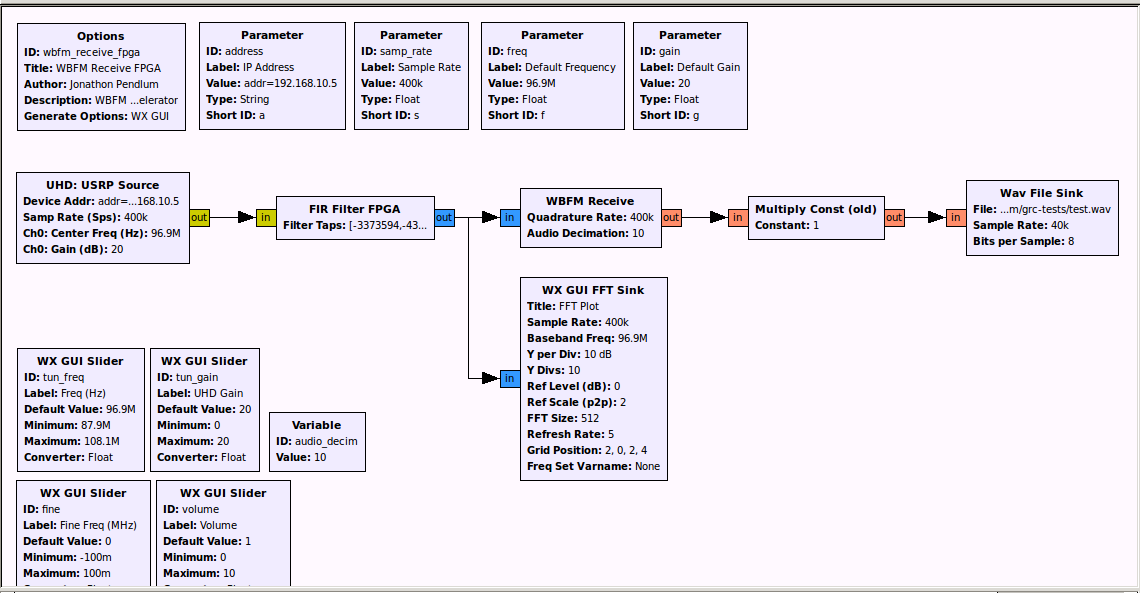
The first image below shows a modified wideband FM radio receiver in GNU Radio Companion with the low pass filter replaced with the FIR Filter FPGA module. The second image shows the receiver tuned to local Boston FM radio station. The images were captured with GNU Radio Companion running on the Zynq hardware via ssh with X11 forwarding enabled. The flow graph can be found in gr-zynq/examples/wbfm_receive_fpga.grc.
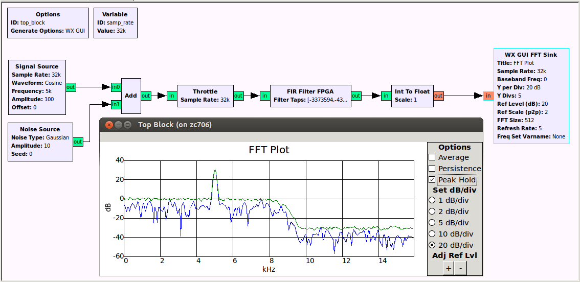
This is an image of the example gr-zynq/examples/fir_filter_fpga_tone_plus_noise_test.grc. The noise source provides a clear outline of the filter's frequency response magnitude.
Performance Analysis
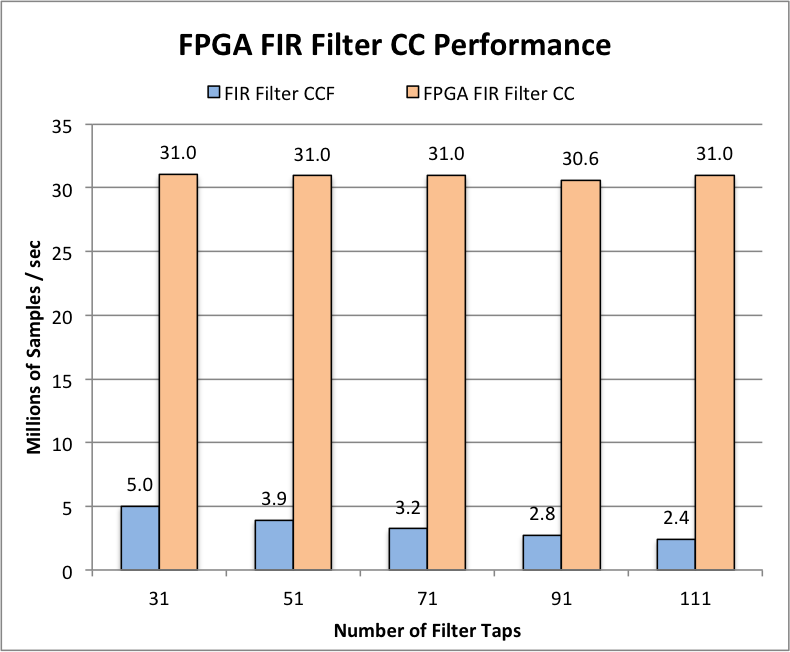
The figure below shows the performance of a built in GNU Radio FIR filter block running on the ARM processor versus the FPGA accelerated FIR filter block. This data was generated on a ZC706 development board using GNU Radio 3.7.1. It is important to note that the performance data for the FPGA accelerated FIR Filter block is affected by data copies between GNU Radio and the kernel buffers, the complex->integer conversions, and data transfer over the AXI bus between the FPGA and the ARM processors. The relatively poor performance of the processor based FIR filter is due to the lack of VOLK kernels for the ARM processor.
The programs used to generate the data can be found in arm-fir-ccf/ and fpga-fir-cc/ in the gr-zynq/examples/performance_tests/ directory.
Appendix A: Build Instructions for the FPGA Bit Stream, First Stage Boot Loader, and BOOT.BIN
Build the FPGA Image
git clone https://www.github.com/jpendlum/zynq-acp.git
cd zynq-acp
git checkout fir-filter-example
cd top/zedboard
source /opt/Xilinx/14.6/ISE_DS/settings64.sh
export PATH=$PATH:/opt/Xilinx/14.6/ISE_DS/ISE/bin/lin64/xtclsh
make
Compiling the FPGA image can take up to an hour.
Build the First Stage Boot Loader
The Zynq devices require an additional boot loader that executes before U-Boot, called the first stage boot loader or FSBL. This boot loader configures low level settings such as the DDR RAM timing.
cd zynq-acp/top/zedboard/build/zynq-ps
xps zedboard_ps.xmp
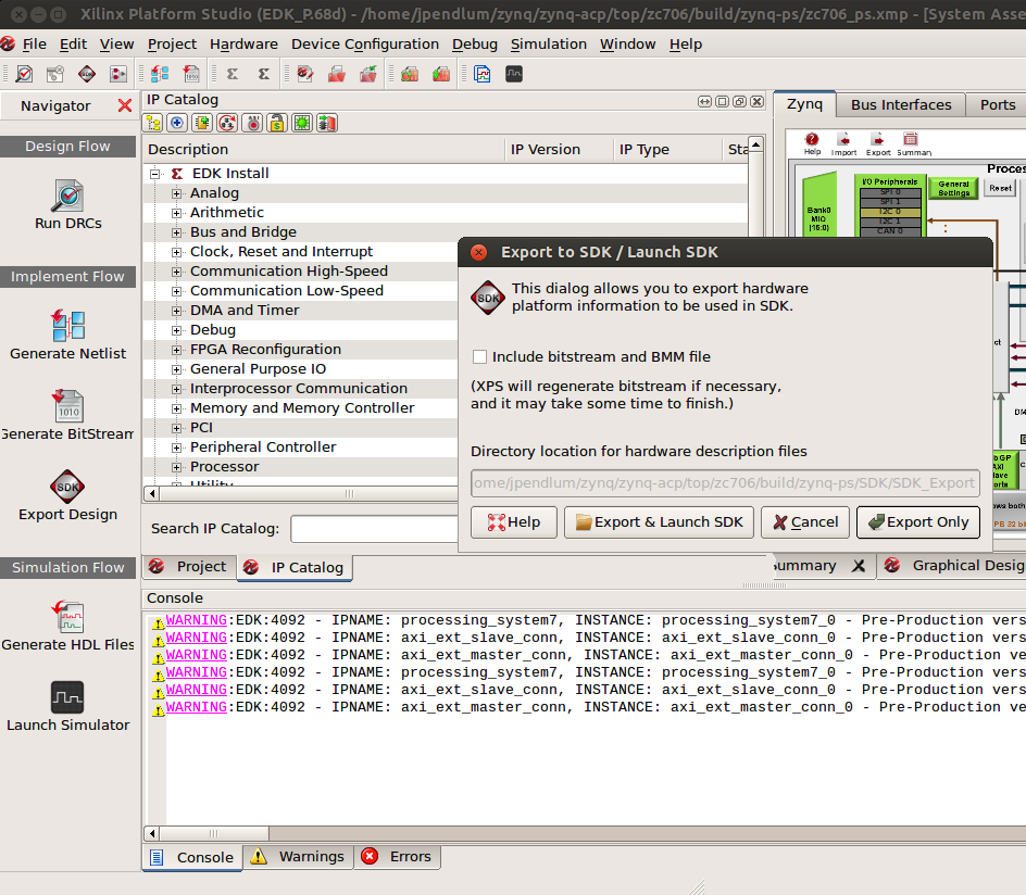
Xilinx's EDK tool will open. The next steps are GUI based.
click "Export Design"
uncheck checkbox "Include bitstream and BMM file"
click "Export & Launch SDK"
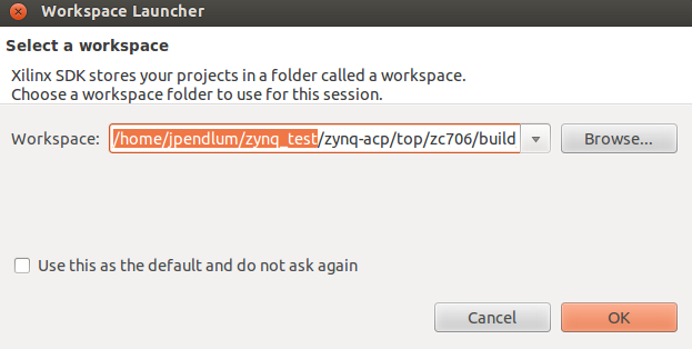
Once Xilinx's Eclipse based SDK program opens, you will be prompted to create a workspace folder. Another script in the instructions requires that the workspace folder be placed in a specific directory: zynq-acp/top/zedboard/build/zynq-ps/SDK/workspace. Make sure to prepend the appropriate path to your Zynq build directory, which is highlighted in the image below for added emphasis.
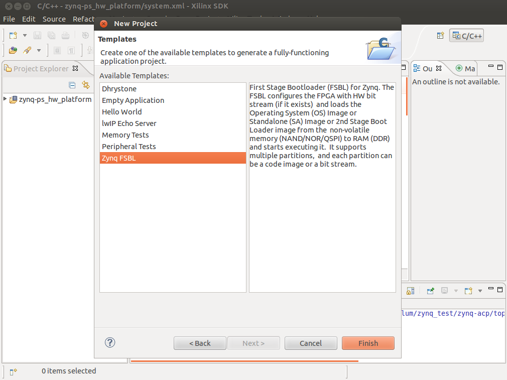
After the program finishes loading:
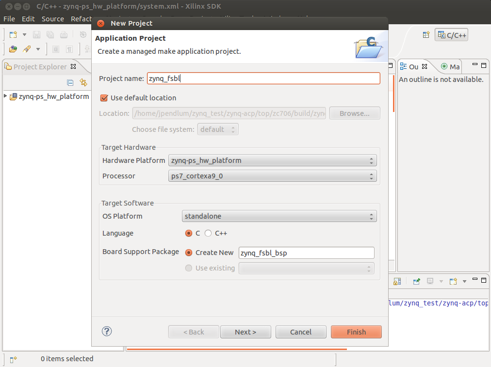
File > New > Application Project
Name "zynq_fsbl"
Click Next >
Select Zynq FSBL
Click Finish
After Xilinx SDK finishes compiling zynq_fsbl.elf, which is needed in the next step to create boot.bin, both programs EDK and XPS are no longer needed and can be closed.
Build BOOT.BIN
When booting the Zynq, it looks for a special file called boot.bin on the SD card. The Xilinx program bootgen creates this file using a configuration file called boot.bif. The script build_boot.sh automates this process.
cd zynq-acp/top/zedboard/boot/
./build_boot.sh
Note: build_boot.sh uses relative paths and assumes the directories zynq-acp and openembedded-core are in the same folder
Appendix B: How to In-System Reconfigure the Zynq's FPGA Fabric with a New FPGA Bit Stream
The Zynq's FPGA fabric can be reconfigured from the command line (on the Zynq device) using xdevcfg. First, generate the .bin file and copy it to the Zynq development board:
cd zynq-acp/top/zedboard/
make promgen
scp build/zedboard.bin someone@zedboard:/home/someone/
Second, determine if the xdevcfg device exists and create it if it does not:
ls /dev/xdevcfg
(If xdevcfg does not exist)
mknod /dev/xdevcfg c 259 0
sudo chmod 666 /dev/xdevcfg
Finally, download the .bin file:
cat zedboard.bin > /dev/xdevcfg
cat /sys/devices/amba.1/f8007000.devcfg/prog_done
(1 = PL programmed successfully)
Note: The prog_done path might be slightly different (such as amba.0 vs amba.1) depending on the system
Appendix C: Alternative Root File System using Linaro Ubuntu Developer Release
The Open Embedded generated rootfs may not be for everyone. If you are more comfortable with the Ubuntu distribution, Linaro provides a developer version of Ubuntu for ARM devices with a working toolchain and apt-get pointing to Ubuntu’s armhf repositories:
wget https://releases.linaro.org/13.08/ubuntu/raring-images/developer/linaro-raring-developer-20130826-474.tar.gz
sudo tar –strip-components=1 -C /media/rootfs -xzpf linaro-raring-developer-20130826-474.tar.gz
cd oe/build/tmp-eglibc/deploy/images/$MACHINE/
sudo tar -C /media/rootfs -xzpf gnuradio-dev-image-$MACHINE.tar.gz ./lib/modules
sudo tar -C /media/rootfs -xzpf gnuradio-dev-image-$MACHINE.tar.gz ./usr/src/
The last two lines from above copied the kernel modules and kernel headers. On first boot, it is advisable to use the USB serial port to set the root password and create a 1GB swap file. You can also apt-get install openssh-server and the window manager openbox.
GNU Radio and UHD will need to be installed from a PPA with an armhf build such as gqrx dev PPA or compiled from source. Compiling from source on the Zynq takes about 14 hours. You will want to make sure to create a 1GB swap file due to GNU Radio's memory usage during the build process. When using cmake, make sure to configure gcc / g++ to optimize for ARM hard float using the line below:
cmake -DCMAKE_CXX_FLAGS:STRING="-march=armv7-a -mtune=cortex-a9 -mfpu=neon -mfloat-abi=hard" -DCMAKE_C_FLAGS:STRING="-march=armv7-a -mtune=cortex-a9 -mfpu=neon -mfloat-abi=hard" ..
Thanks
The GNU Radio Zynq support was the result of the 2013 Google Summer of Code project GnuRadio FPGA Co-processing with the Xilinx Zynq System-on-Chip with mentor Philip Balister and student Jonathon Pendlum and a hardware donation from Xilinx.
Jonathon Pendlum is a graduate student at Northeastern University and member of the Reconfigurable Computing Laboratory headed by his advisor Professor Miriam Leeser.
A big thanks goes to Moritz Fischer for his invaluable help with the device driver and FPGA infrastructure.
