FM Deemphasis: Difference between revisions
(Created page with "Category:Block Docs Category:Stub Docs This is the template for the "Page-per-block Docs". This first section should describe what the block...") |
m (test edit) |
||
| (2 intermediate revisions by 2 users not shown) | |||
| Line 1: | Line 1: | ||
[[Category:Block Docs]] | [[Category:Block Docs]] | ||
An analog deemphasis filter: | |||
R | |||
o------/\/\/\/---+----o | |||
| | |||
= C | |||
| | |||
--- | |||
Has this transfer function: | |||
1 1 | |||
---- --- | |||
RC tau | |||
H(s) = ---------- = ---------- | |||
1 1 | |||
s + ---- s + --- | |||
RC tau | |||
And has its -3 dB response, due to the pole, at | |||
|H(j w_c)|^2 = 1/2 => s = j w_c = j (1/(RC)) | |||
Historically, this corner frequency of analog audio deemphasis filters | |||
been specified by the RC time constant used, called tau. | |||
So w_c = 1/tau. | |||
FWIW, for standard tau values, some standard analog components would be: | |||
tau = 75 us = (50K)(1.5 nF) = (50 ohms)(1.5 uF) | |||
tau = 50 us = (50K)(1.0 nF) = (50 ohms)(1.0 uF) | |||
In specifying tau for this digital deemphasis filter, tau specifies | |||
the *digital* corner frequency, w_c, desired. | |||
The digital deemphasis filter design below, uses the | |||
"bilinear transformation" method of designing digital filters: | |||
1. Convert digital specifications into the analog domain, by prewarping digital frequency specifications into analog frequencies. | |||
w_a = (2/T)tan(wT/2) | |||
2. Use an analog filter design technique to design the filter. | |||
3. Use the bilinear transformation to convert the analog filter design to a digital filter design. | |||
H(z) = H(s)| | |||
s = (2/T)(1-z^-1)/(1+z^-1) | |||
w_ca 1 1 - (-1) z^-1 | |||
H(z) = ---- * ----------- * ----------------------- | |||
2 fs -w_ca -w_ca | |||
1 - ----- 1 + ----- | |||
2 fs 2 fs | |||
1 - ----------- z^-1 | |||
-w_ca | |||
1 - ----- | |||
2 fs | |||
We use this design technique, because it is an easy way to obtain a filter design with the -6 dB/octave roll-off required of the deemphasis filter. | |||
Jackson, Leland B., _Digital_Filters_and_Signal_Processing_Second_Edition_, | |||
Kluwer Academic Publishers, 1989, pp 201-212 | |||
Orfanidis, Sophocles J., _Introduction_to_Signal_Processing_, Prentice Hall, | |||
1996, pp 573-583 | |||
== Parameters == | == Parameters == | ||
; | ; Sample Rate | ||
: | : Sampling frequency in Hz | ||
; | ; Tau | ||
: | : Time constant in seconds (75us in US, 50us in EUR) | ||
== Example Flowgraph == | == Example Flowgraph == | ||
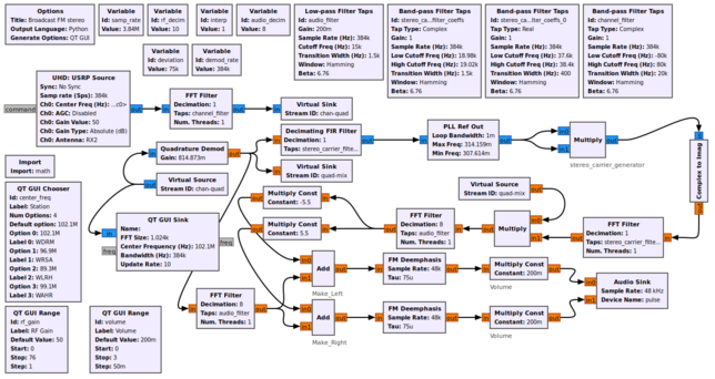
This flowgraph implements a Broadcast FM stereo receiver using basic blocks. | |||
[[File:USRP_FM_stereo_fg.png|644px]] | |||
== Source Files == | == Source Files == | ||
; | ; Python files | ||
: [https://github.com/gnuradio/gnuradio | : [https://github.com/gnuradio/gnuradio/blob/master/gr-analog/python/analog/fm_emph.py] | ||
; Block definition | ; Block definition | ||
: [https://github.com/gnuradio/gnuradio | : [https://github.com/gnuradio/gnuradio/blob/master/gr-analog/grc/analog_fm_deemph.block.yml] | ||
Latest revision as of 04:53, 24 January 2022
An analog deemphasis filter:
              R
   o------/\/\/\/---+----o
                  |
                 = C
                  |
                 ---
Has this transfer function:
              1             1
             ----          ---
              RC          tau
   H(s) = ---------- = ----------
                1             1
           s + ----      s + ---
                RC           tau
And has its -3 dB response, due to the pole, at
|H(j w_c)|^2 = 1/2 => s = j w_c = j (1/(RC))
Historically, this corner frequency of analog audio deemphasis filters been specified by the RC time constant used, called tau. So w_c = 1/tau.
FWIW, for standard tau values, some standard analog components would be:
   tau = 75 us = (50K)(1.5 nF) = (50 ohms)(1.5 uF)
   tau = 50 us = (50K)(1.0 nF) = (50 ohms)(1.0 uF)
In specifying tau for this digital deemphasis filter, tau specifies the *digital* corner frequency, w_c, desired.
The digital deemphasis filter design below, uses the "bilinear transformation" method of designing digital filters:
1. Convert digital specifications into the analog domain, by prewarping digital frequency specifications into analog frequencies.
w_a = (2/T)tan(wT/2)
2. Use an analog filter design technique to design the filter.
3. Use the bilinear transformation to convert the analog filter design to a digital filter design.
H(z) = H(s)|
                s = (2/T)(1-z^-1)/(1+z^-1)
        w_ca         1          1 - (-1) z^-1
   H(z) = ---- * ----------- * -----------------------
        2 fs        -w_ca             -w_ca
                1 - -----         1 + -----
                     2 fs              2 fs
                              1 - ----------- z^-1
                                      -w_ca
                                  1 - -----
                                       2 fs
We use this design technique, because it is an easy way to obtain a filter design with the -6 dB/octave roll-off required of the deemphasis filter.
Jackson, Leland B., _Digital_Filters_and_Signal_Processing_Second_Edition_, Kluwer Academic Publishers, 1989, pp 201-212
Orfanidis, Sophocles J., _Introduction_to_Signal_Processing_, Prentice Hall, 1996, pp 573-583
Parameters
- Sample Rate
- Sampling frequency in Hz
- Tau
- Time constant in seconds (75us in US, 50us in EUR)
Example Flowgraph
This flowgraph implements a Broadcast FM stereo receiver using basic blocks.
Source Files
- Python files
- [1]
- Block definition
- [2]
