User:CSeguinot: Difference between revisions
No edit summary |
No edit summary |
||
| Line 3: | Line 3: | ||
This tutorial is intended for non specialist, it involves as less maths as possible and present most results with GNURadio flowgraph. Some examples involving simple modulation scheme used in HAM radio are presented. While introducing complex signal can be seen as increasing complexity, we will see that it drastically simplify | This tutorial is intended for non specialist, it involves as less maths as possible and present most results with GNURadio flowgraph. Some examples involving simple modulation scheme used in HAM radio are presented. While introducing complex signal can be seen as increasing complexity, we will see that it drastically simplify studying impairment such as synchronization. | ||
If you are searching for more detailed information please refer to corresponding literature such as references [[#ancre1|[1]]],[[#ancre2|[2]]],[[#ancre3|[3]]]. | If you are searching for more detailed information please refer to corresponding literature such as references [[#ancre1|[1]]],[[#ancre2|[2]]],[[#ancre3|[3]]]. | ||
| Line 80: | Line 80: | ||
* look at the spectrum shape for sawtooth input and random bit sequence (QT Gui chooser and Selector) | * look at the spectrum shape for sawtooth input and random bit sequence (QT Gui chooser and Selector) | ||
* When transmitting random bits, you can desactivate the interpolating FIR Filter and replace it by a root raised cosine filter | * When transmitting random bits, you can desactivate the interpolating FIR Filter and replace it by a root raised cosine filter | ||
== Spectrum properties of signals== | |||
Amplitude spectrum is calculated using the Fourier Transform. It represents how the power is spread in the frequency domain. It allows for determining the signal bandwidth. Power Spectral Density or PSD correspond to the average magnitude of the Amplitude spectrum. | |||
In this section we summarize some properties of the phase arg''{X(f)}'' and magnitude |''X(f))''|. We first consider properties for continuous signal. Then we will investigate additional properties of sampled signal (those used in GNURadio). | |||
Given a signal ''x(t)"" it amplitude/phase spectrum is denoted ''X(f))'' which is a complex function given by : | |||
: <math>X(f) =\int{x(t)e^{-2j\pi ft}dt</math> | |||
=== continuous real signal === | |||
Every real signal have a spectrum whose magnitude is symmetric and phase is anti-symmetric. | |||
: <math>x(t) \in \mathbb{R}</math> | |||
: <math>X(-f)=X^*(f)</math> | |||
: <math>|X(-f)|=|X(f)|</math> | |||
: <math>\text{arg}\{X(-f)\}=-\text{arg}\{X(f)\}</math> | |||
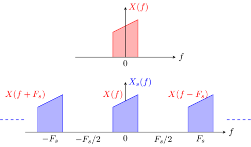
[[File:IQ_complex_tutorial_complex_spectrum.png|thumb|500px|Complex signal spectrum and, sampled complex signal spectrum (only first 3 patterns represented)]] | |||
=== continuous complex signal === | |||
The main difference with real signal is that: | |||
* any complex signal having non null imaginary part exhibits a non-symmetric spectrum. | |||
* as a consequence, every non-symmetric spectrum correspond to a complex signal | |||
=== sampled signals === | |||
We consider a signal ''x(t))'' and we note its sampled version ''x<sub>s</sub>(t))'' sampled at frequency ''F<sub>s</sub>''. | |||
The spectrum ''X<sub>s</sub>(f)'' of the sampled signal is a periodic function of period ''F<sub>s</sub>''. | |||
: <math>X_s(f)=\sum_k X(f-kF_s)</math> | |||
So the sampled signal spectrum verify : | |||
: <math>X_s(f+kF_s)=X_s(f)</math> | |||
Generally the bandwidth of ''X(f))'' is lower then ''F<sub>s</sub>''/2. The infinite sum defined above exhibit no aliasing (no superposition of patterns ''X(f), X(f+F<sub>s</sub>)'' and ''X(f-F<sub>s</sub>)'') .In that case, as stated in the Nyquist theorem of sampling, the original spectrum/signal can be recovered by filtering the sampled signal. | |||
When the maximum frequency of the signal spectrum do not respect Nyquist theorem, one should filter the signal with a low pass filter having a cutt-off frequency lower then ''F<sub>s</sub>''/2 before sampling: this correspond to the anti-aliasing filter used in every SDR hardware. | |||
== Complex enveloppe, equivalent baseband signal== | == Complex enveloppe, equivalent baseband signal== | ||
| Line 170: | Line 203: | ||
AM modulation is a special case for which the equivalent baseband complex signal has a null imaginary part and is real. Considering the schematic diagram of an IQ modulator demodulator, when ''q(t))'' is null the diagram is simplified (imaginary path is not used) yielding the well known AM modulation/demodulation scheme. | AM modulation is a special case for which the equivalent baseband complex signal has a null imaginary part and is real. Considering the schematic diagram of an IQ modulator demodulator, when ''q(t))'' is null the diagram is simplified (imaginary path is not used) yielding the well known AM modulation/demodulation scheme. | ||
Remind that in GNURadio flowgraph : | |||
* orange connections correspond to real signals (float numbers) | |||
* blue connections correspond to complex signals (complex numbers) | |||
Flowgraph [[media:IQ_tutorial_AM_TX_complex.grc|IQ_tutorial_AM_TX_complex.grc]] contains two equivalent diagram for an AM modulation with a sawtooth input: | Flowgraph [[media:IQ_tutorial_AM_TX_complex.grc|IQ_tutorial_AM_TX_complex.grc]] contains two equivalent diagram for an AM modulation with a sawtooth input: | ||
| Line 192: | Line 229: | ||
You can now run this flowgraph and compare signal and their spectrum in both modulator. Once again, these simulations suppose perfectly synchronous emitter and receiver carrier which is quite far from reality. | You can now run this flowgraph and compare signal and their spectrum in both modulator. Once again, these simulations suppose perfectly synchronous emitter and receiver carrier which is quite far from reality. | ||
==== Further work : construct the demodulator flowgraph ==== | ==== Further work : construct the AM demodulator flowgraph ==== | ||
Use the flowgraph IQ_tutorial_AM_TX_complex_2.grc that you created, add blocks to perform AM demodulation and to recover the input signal ''a(t)'' from the modulated signal. You have to use the equivalent baseband representation of the demodulator. | Use the flowgraph IQ_tutorial_AM_TX_complex_2.grc that you created, add blocks to perform AM demodulation and to recover the input signal ''a(t)'' from the modulated signal. You have to use the equivalent baseband representation of the demodulator. | ||
{| class="mw-collapsible mw-collapsed wikitable" | {| class="mw-collapsible mw-collapsed wikitable" | ||
| 1st indication | |||
|- | |- | ||
| Remind and use the relation between ''a(t)'' and ''c(t)=i(t)+jq(t)'' given above. | | Remind and use the relation between ''a(t)'' and ''c(t)=i(t)+jq(t)'' given above. | ||
| Line 202: | Line 239: | ||
{| class="mw-collapsible mw-collapsed wikitable" | {| class="mw-collapsible mw-collapsed wikitable" | ||
| 2nd indication | |||
|- | |- | ||
| An AM demodulator extract the amplitude (magnitude) of the modulated signal... | | An AM demodulator extract the amplitude (magnitude) of the modulated signal... | ||
| Line 208: | Line 245: | ||
{| class="mw-collapsible mw-collapsed wikitable" | {| class="mw-collapsible mw-collapsed wikitable" | ||
| Solution including filter | |||
|- | |- | ||
| [[media:IQ_tutorial_AM_TX_complex_3.grc|IQ_tutorial_AM_TX_complex_3.grc]] | | [[media:IQ_tutorial_AM_TX_complex_3.grc|IQ_tutorial_AM_TX_complex_3.grc]] | ||
| Line 239: | Line 276: | ||
* Disable the interpolating filters and enable both root raised cosine filter (the filter used in every QPSK emitter). This yields the real spectrum of a QPSK. | * Disable the interpolating filters and enable both root raised cosine filter (the filter used in every QPSK emitter). This yields the real spectrum of a QPSK. | ||
== | == Equivalent baseband scheme == | ||
This section is not yet ready... Work in progress !! | |||
This diagram sketch a classical Emitter/Receiver (Tx/Rx) transmission including channel noise, and its equivalent baseband representation which could be used for a GNURadio simulation. | |||
Note that complex baseband signal don't permit precise modelization of non linear effects such as intermodulation so they are not considered here. Every linear band limited system has an equivalent baseband as despicted below. | |||
=== Bandpass filter=== | === Bandpass filter=== | ||
* give the equivalent baseband representation of a bandpass filter | |||
* explain what is a complex filter and when a filter is complex | |||
=== Unsynchronized demodulator === | === Unsynchronized demodulator === | ||
* give the equivalent baseband representation of an unsynchronized receiver (using results obtained above) | |||
=== Channel noise === | === Channel noise === | ||
* give the equivalent baseband representation of noise source | |||
The | * explain what is a complex noise. | ||
== Tx/Rx QPSK : the carrier asynchronism problem == | |||
This section is not yet ready... Work in progress !! | |||
The idea of this section is to explain what is carrier asynchronism, how it can be simulated in GNURadio, and the basic mechanism to compensate it in a receiver. | |||
== | === GNURadio Channel model === | ||
* explain how carrier asynchronism is simulated with the channel model | |||
* give a flowgraph illustrating the problem (with the QPSK used above) | |||
* give a basic solution to compensate carrier asynchronism by muttiplying by exp(2 j pi df t) | |||
=== GNURadio XLating filter === | |||
* explain the Xlating mecanism, spectrum cycling-shifted | |||
* give a basic solution to compensate carrier asynchronism with a Xlating filter | |||
* note that this solution is basic and not sufficient in real hardware | |||
=== Asynchronism in real hardware === | |||
* give a recorded example of unmodulated carrier emitted and received by a SDR Dongle | |||
* try to compensate asynchronism | |||
* result : we need more robust block to synchronize: see PSK guided tutorial ... | |||
==References== | ==References== | ||
Latest revision as of 14:58, 28 January 2021
This tutorial originates from discussions on discuss-gnuradio@gnu.org. We will explain why simulating digital communications requires equivalent baseband representation of signal which in fact are complex signals. For this unique reason, complex signals are essential in GNURadio.
This tutorial is intended for non specialist, it involves as less maths as possible and present most results with GNURadio flowgraph. Some examples involving simple modulation scheme used in HAM radio are presented. While introducing complex signal can be seen as increasing complexity, we will see that it drastically simplify studying impairment such as synchronization.
If you are searching for more detailed information please refer to corresponding literature such as references [1],[2],[3].
Some maths
This section summarize complex numbers properties used in this tutorial. More information can be found on complex number Wikipedia page||200px.
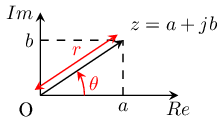
A complex number is a number of the form a + jb, where a and b are real numbers, and j is an indeterminate satisfying j2=-1 (Mathematician prefer using i instead of j used by physicist and radio engineers). For example, z1=2+3j is a complex number. The real part Re{z} of z1 is 2 and its imaginary part Im{z} is 3.
Complex numbers can be represented in the complex plane as vectors. The modulus or magnitude r of a complex number z = a + jb is
The phase φ of z mathematically referred to as the argument is the angle of the radius Oz with the positive real axis.
- (for a≠0)
Together, r and φ give another way of representing complex numbers, the polar form and the exponential form.
The exponential form is convenient for computing the multiplication of two complex numbers.
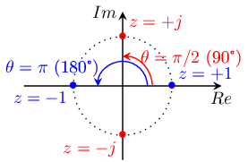
Following complex number have a unit magnitude r=1 :
A complex signal c(t) can be seen as two real signal i(t), q(t) combined to create a complex signal. It can also be represented by its time varying amplitude a(t) and its phase φ(t)
Why we need complex and IQ signals
GNURadio software is mainly used to design and study radio communications. Making high frequency transmission requires modulating a high frequency carrier at frequency F0. The most common modulation for analog transmissions are Amplitude modulation (AM) Phase modulation (PM) and Frequency modulation (FM).
For analog AM, the modulated signal m(t) is simply the mathematical product of the carrier c(t) and the baseband signal to transmit a(t). The corresponding hardware is a mixer whose scheme and mathematical representation is a multiplier.
We call a(t) a baseband signal since its spectrum is in a low frequency range starting near 0 Hz (For example [0-20kHz] for an HIFI audio signal).
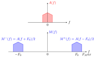
The spectrum of an AM modulated signal M(f) is the translation or the audio spectrum A(f) around ±F0 with A(f) being the entire spectrum of the modulating signal, using both positive and negative frequencies
N.B. Negative frequencies are often omitted in spectrum representation since, for real signal (a(t), m(t) are real) the power spectrum are symmetric around zero as will be detailed later.
Up to now we have been dealing with real signal. The need for complex signal appears in the next step. Simulation requires sampled signal. Sampling is the operation of observing a continuous signal and taking a finite number of sample at a given sampling rate fs (i.e; one sample each 1/fs second). simulator can only make calculations on a finite number of samples, they require sampled signal. Nyquist Sampling theorem states that the sampling rate must be greater than twice the maximum frequency FMax to be able to reconstruct the original signal from the sampled signal.
For an HIFI audio signal, maximum audio frequency is closed to 20 kHz, sampling rate must be higher then 40 kHz (44.8 kHz is often used in computer sound card, 8 kHz is used for mobile phone since voice has a lower frequency range then HIFI audio).
For an AM signal modulated by an audio signal, maximum frequency of the modulated spectrum is . Direct sampling of such signal is not possible with conventional hardware such as low cost SDR dongle. If the carrier frequency is close to 1 GHz, the sampling rate should be at least 2 GHz. This is obviously too much then computer can handle (higher then some computer clock).
Flowgraph IQ_tutorial_AM_TX_real.grc illustrates amplitude modulation using only real blocks (excepted for bits source). As a consequence, the maximum carrier frequency is limited to several tens of kHz.
- study the modulator part which simply multiply the baseband signal and the sine carrier
- look at the influence of the carrier frequency on the modulated signal spectrum (carrier frequency must stay lower than half the sampling rate)
- look at the spectrum shape for sawtooth input and random bit sequence (QT Gui chooser and Selector)
- When transmitting random bits, you can desactivate the interpolating FIR Filter and replace it by a root raised cosine filter
Spectrum properties of signals
Amplitude spectrum is calculated using the Fourier Transform. It represents how the power is spread in the frequency domain. It allows for determining the signal bandwidth. Power Spectral Density or PSD correspond to the average magnitude of the Amplitude spectrum.
In this section we summarize some properties of the phase arg{X(f)} and magnitude |X(f))|. We first consider properties for continuous signal. Then we will investigate additional properties of sampled signal (those used in GNURadio).
Given a signal x(t)"" it amplitude/phase spectrum is denoted X(f)) which is a complex function given by :
- Failed to parse (syntax error): {\displaystyle X(f) =\int{x(t)e^{-2j\pi ft}dt}
continuous real signal
Every real signal have a spectrum whose magnitude is symmetric and phase is anti-symmetric.
continuous complex signal
The main difference with real signal is that:
- any complex signal having non null imaginary part exhibits a non-symmetric spectrum.
- as a consequence, every non-symmetric spectrum correspond to a complex signal
sampled signals
We consider a signal x(t)) and we note its sampled version xs(t)) sampled at frequency Fs.
The spectrum Xs(f) of the sampled signal is a periodic function of period Fs.
So the sampled signal spectrum verify :
Generally the bandwidth of X(f)) is lower then Fs/2. The infinite sum defined above exhibit no aliasing (no superposition of patterns X(f), X(f+Fs) and X(f-Fs)) .In that case, as stated in the Nyquist theorem of sampling, the original spectrum/signal can be recovered by filtering the sampled signal.
When the maximum frequency of the signal spectrum do not respect Nyquist theorem, one should filter the signal with a low pass filter having a cutt-off frequency lower then Fs/2 before sampling: this correspond to the anti-aliasing filter used in every SDR hardware.
Complex enveloppe, equivalent baseband signal
Baseband signals have a spectrum at low frequency near 0 Hz. Audio, video and NRZ line code are baseband signals.
Bandpass signals have no energy near 0 Hz and a spectrum located near a high frequency (generally the carrier frequency). Analog and digital AM PM and FM modulated signals are bandpass signals.
A theorem ([1],[2],[3]) states that any high frequency bandpass signal having a limited bandwidth B can be represented by a baseband equivalent signal having the same bandwidth. This baseband equivalent signal also called the complex envelope is used in simulators since its allow to lower sampling rate as compare to directly sampling the bandpass signal.
The equivalent baseband representation help us for the simulation of bandpass signals. At this step we need some math. We will consider a carrier modulated in phase and/or amplitude (in the sake of simplicity, Frequency modulation is not considered but it can be related to phase modulation.). Such a modulated signal m(t) and it's complex representation is :
For modulated signal, the complex representation is obtained by replacing the cos function by an exponent function . For a more general definition see [1],[2],[3] . The real signal correspond to the real part of the complex signal .
One important property of spectrum is that it has only energy in the positive frequency range and verify.
where denotes the restriction of to the positive frequency range.
Let us now look at the complex envelope or equivalent baseband signal of bandpass signal defined by :
Multiplying a signal by correspond to a frequency translation of the spectrum so that we have:
So the spectrum of the complex enveloppe is a baseband signal whose spectrum has the same shape as . For this reason, knowing or is sufficient to reconstruct or .
IQ modulator and demodulator
Let us now come to hardware and SDR and first rewrite the equivalent baseband signal and the modulated signal m(t) :
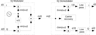
The phase φ(t) of the modulated signal m(t), is identical to the phase of the complex signal c(t)=i(t)+jq(t). The equivalent baseband signal c(t) is represented in a complex plane also refeered to as the IQ plane. The resulting m(t) can be any modulated in AM, PM or even FM signal.
As a result, the modulated signal m(t) is the addition of :
- which is an AM modulated signal, the product of i(t) by a signal In phase with the carrier (i stand for In phase)
- which is an AM modulated signal, the product of q(t) by a signal in Quadrature with the carrier (q stand for Quadrature)
The corresponding hardware is called an IQ modulator. Every modern radio communication uses IQ modulator for emitting and IQ demodulator for receiving. The IQ demodulator is able to recover incoming i(t) and q(t). If the amplitude of the recovered carrier is 2, and if modulator and demodulator carrier are synchronous (same frequency and phase) the output of the IQ demodulator correspond to input i(t) and q(t).
In real hardware, carrier are not synchronous and the receiver must compensate any phase and frequency difference between emitter and receiver. This is done using some hardware and/or software such as polyphase clock sync, and Costas loop.
SDR Module such as USRP N320 block Diagram) and SDR Dongle (RTL-2832) input and output are the 2 real signals i(t) and q(t) combined to form the complex signal i(t) + j q(t) which turns to be the equivalent baseband of the modulated emitted or received signal. These hardware are based on IQ modulator and IQ demodulator associated with mixers when intermediate frequency (IF) is used.
Some examples of EqBB signals
In order to get familiar with complex signal, let us consider some basic examples.
First, we suppose our emitter carrier is so that every equivalent baseband signal will be defined according to this reference.
complex envelope of a pure sine wave
We will consider a pure sine wave, close to the carrier having a Δf frequency shift and φ phase shift as compared to the carrier. After some math we get its complex equivalent signal.
The complex envelope of the carrier itself is found for Δf=0 and φ=0 which yields . We conclude that in a GNURadio flowgraph, the carrier is represented by a continuous components, a pure DC signal ; this may seemed counter intuitive. The spectrum is a single peak at f=0 which can be represented using the Dirac δ(f) function (or distribution) : . Shifting this spectrum of towards positive frequency we get the positive part of the carrier spectrum (a peak at ) : . The negative part of the spectrum is simply obtained by symmetry of the real part (a peak at ).
This can be simulated with GNURadio flowgraph IQ_tutorial_eq_bb.grc. The spectrum of our carrier is centered at 0 Hz. The Frequency sink has a feature to shift this spectrum around which is a parameter of the sink. In a simulation, it is not necessary to represent the negative part of the spectrum since m(t) being real, it spectrum is obviously symmetric.
We will now consider Δf ≠0 which simulate a signal not exactly synchronous to the carrier. This yieds
The complex enveloppe is rotating vector (you can simulate this with Δf=1 Hz giving a vector which rotate at 60 rpm or 1 turn per second) , its spectrum is a single peak at f=+Δf. This complex signal exhibits a non symmetric spectrum (no peak at f=-Δf). Change Δf to -0.5 Hz, the vector now rotates counter clockwise at 30 rpm or 0.5 turn per second.
Exercice: Open flowgraph IQ_tutorial_eq_bb.grc. Parameter delta_f is set with an increment of 1/12, which correspond to 5 rotation per minute.
- For Δf=1/12=0.0833, what is the speed of rotation of the complex signal?
- What do you observe when Δf=-1/12=-0.0833 ?
- Slowly increase Δf to reach fs/2 and observe the spectrum really has a single peak at Δf. Explain your observation when Δf>fs/2'.
- Do the same for a negative Δf
- For Δf =fs what is the equivelant baseband frequency. What is the carrier frequency ?
- Set Δf=0 and φ≠0. Discusss the simulated equivalent baseband signal.
AM mod demod example
This example will consider signal baseband signal a(t) modulating a carrier at F0 in AM, and its demodulation. As no phase modulation in used, φ(t)=0 and consequently q(t)=0.
AM modulation is a special case for which the equivalent baseband complex signal has a null imaginary part and is real. Considering the schematic diagram of an IQ modulator demodulator, when q(t)) is null the diagram is simplified (imaginary path is not used) yielding the well known AM modulation/demodulation scheme.
Remind that in GNURadio flowgraph :
- orange connections correspond to real signals (float numbers)
- blue connections correspond to complex signals (complex numbers)
Flowgraph IQ_tutorial_AM_TX_complex.grc contains two equivalent diagram for an AM modulation with a sawtooth input:
- the upper one uses real signals. It is the exact AM modulator uses at the beginning of this tutorial.
- sampling frequency is 200 kHz, 40 times the input rate which equal 5 kHz.
- allowing a maximum carrier frequency close to 100Khz
- the lower one uses an equivalent baseband representation.
- sampling frequency is 25 kHz, 5 times the input rate which equal 5 kHz.
- the sawtoooth correspond to identical generator in both modulator
- each blue input or output is the baseband equivalent of the corresponding signal in the upper AM modulator.
- the carrier frequency can be any value compatible with connected Hardware
- the carrier equivalent signal equal 1 (as stated in the previous section) so it has been disable and replaced by a complex constant
- the Hardware input is the complex equivalent baseband signal
- the carrier frequency is not needed nor used in complex blocks; excepted in the QT GUI spectrum to label the center frequency which is 0 but correspond to the F>sub>0.
Three blocks are unusefull and can be removed from the lower complex modulator:
- save the current flowgraph as IQ_tutorial_AM_TX_complex_2.grc.
- remove the complex multiplier, the carrier equivalent baseband (complex constant=1) and the carrier complex source (the disabled one). Reconnect complex to float and throttle blocks to obtain the flowgraph sketched on the right.
You can now run this flowgraph and compare signal and their spectrum in both modulator. Once again, these simulations suppose perfectly synchronous emitter and receiver carrier which is quite far from reality.
Further work : construct the AM demodulator flowgraph
Use the flowgraph IQ_tutorial_AM_TX_complex_2.grc that you created, add blocks to perform AM demodulation and to recover the input signal a(t) from the modulated signal. You have to use the equivalent baseband representation of the demodulator.
| 1st indication |
| Remind and use the relation between a(t) and c(t)=i(t)+jq(t) given above. |
| 2nd indication |
| An AM demodulator extract the amplitude (magnitude) of the modulated signal... |
| Solution including filter |
| IQ_tutorial_AM_TX_complex_3.grc
Running this flowgraph, demodulation is obtained taking the real part (imperfect solution), or the magnitude (good solution) of the complex signal.
|
QPSK example
QPSK digital signal exhibit four phase state .
And the baseband equivalent signal also exhibit 4 different values each one being used to code a 2 bits sequence 00 01 10 or 11 :
Normally, we would use a GNURadio "constellation modulator" to simulate QPSK as is done in the excellent Guided Tutorial on PSK Demodulation.
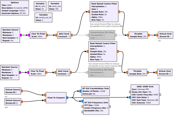
For the present tutorial we will simulate a QPSK without Nyquist filter in order to get phase states which can be simply displayed on a constellation sink. This is not possible with constellation modulator. Our QPSK modulator (complex representation) is build taking into account that the complex signal exhibit 4 different values, its obvious that both i(t) and q(t) have only 2 states so they are binary symmetric NRZ line codes:
Flowgraph IQ_tutorial_QPSK.grc generates 2 sequences of bits, interpolates them to get 2 binary symmetric NRZ line codes. The NRZ signals are combined to create the complex equivalent baseband signal of the QPSK which can be transmitted to any SDR emitter.
Simulate this flowgraph :
- stop the QT GUI spectrum to observe that the complex baseband signal spectrum is no longer symmetric as expected for complex signals.
- use spectrum averaging to see that despite of the previous observation, the power spectral density (average of the magnitude spectrum) is symmetric around 0 (which correspond to F0 for the modulated signal.
- Disable the interpolating filters and enable both root raised cosine filter (the filter used in every QPSK emitter). This yields the real spectrum of a QPSK.
Equivalent baseband scheme
This section is not yet ready... Work in progress !!
This diagram sketch a classical Emitter/Receiver (Tx/Rx) transmission including channel noise, and its equivalent baseband representation which could be used for a GNURadio simulation.
Note that complex baseband signal don't permit precise modelization of non linear effects such as intermodulation so they are not considered here. Every linear band limited system has an equivalent baseband as despicted below.
Bandpass filter
- give the equivalent baseband representation of a bandpass filter
- explain what is a complex filter and when a filter is complex
Unsynchronized demodulator
- give the equivalent baseband representation of an unsynchronized receiver (using results obtained above)
Channel noise
- give the equivalent baseband representation of noise source
- explain what is a complex noise.
Tx/Rx QPSK : the carrier asynchronism problem
This section is not yet ready... Work in progress !!
The idea of this section is to explain what is carrier asynchronism, how it can be simulated in GNURadio, and the basic mechanism to compensate it in a receiver.
GNURadio Channel model
- explain how carrier asynchronism is simulated with the channel model
- give a flowgraph illustrating the problem (with the QPSK used above)
- give a basic solution to compensate carrier asynchronism by muttiplying by exp(2 j pi df t)
GNURadio XLating filter
- explain the Xlating mecanism, spectrum cycling-shifted
- give a basic solution to compensate carrier asynchronism with a Xlating filter
- note that this solution is basic and not sufficient in real hardware
Asynchronism in real hardware
- give a recorded example of unmodulated carrier emitted and received by a SDR Dongle
- try to compensate asynchronism
- result : we need more robust block to synchronize: see PSK guided tutorial ...
References
Further reading for complex equivalent baseband signal:
- [1] Proakis J., Digital Communication, McGraw Hill Series in Electrical and Computer Engineering, Singapore, 1989
- [2] Gallager R., Principles of digital communication, Cambridge University Press Cambridge, UK, 2008
- [3] Benedetto S. and Biglieri E., Principles of digital transmission : with wireless applications, Kluwer Academic/Plenum Publishers, NY, 1999









![{\displaystyle m(t)={\text{Re}}\left[{\big (}i(t)+jq(t){\big )}e^{j2\pi F_{0}t}\right]}](https://en.wikipedia.org/api/rest_v1/media/math/render/svg/bbfb1dabf2f6e18dd0c93c8b2f20ba6e43bae6de)


