FM Preemphasis
An analog preemphasis filter, that flattens out again at the high end:
              C
        +-----||------+
        |             |
   o------+             +-----+--------o
        |      R1     |     |
        +----/\/\/\/--+     \
                            /
                            \ R2
                            /
                            \
                            |
   o--------------------------+--------o
(This fine ASCII rendition is based on Figure 5-15 in "Digital and Analog Communication Systems", Leon W. Couch II)
Has this transfer function:
                  1
             s + ---
                 R1C
   H(s) = ------------------
              1       R1
         s + --- (1 + --)
             R1C      R2
It has a corner due to the numerator, where the rise starts, at
|Hn(j w_cl)|^2 = 2*|Hn(0)|^2 => s = j w_cl = j (1/(R1C))
It has a corner due to the denominator, where it levels off again, at
|Hn(j w_ch)|^2 = 1/2*|Hd(0)|^2 => s = j w_ch = j (1/(R1C) * (1 + R1/R2))
Historically, the corner frequency of analog audio preemphasis filters been specified by the R1C time constant used, called tau.
So w_cl = 1/tau = 1/R1C; f_cl = 1/(2*pi*tau) = 1/(2*pi*R1*C) w_ch = 1/tau2 = (1+R1/R2)/R1C; f_ch = 1/(2*pi*tau2) = (1+R1/R2)/(2*pi*R1*C)
and note f_ch = f_cl * (1 + R1/R2).
For broadcast FM audio, tau is 75us in the United States and 50us in Europe. f_ch should be higher than our digital audio bandwidth.
The Bode plot looks like this:
                    /----------------
                   /
                  /  <-- slope = 20dB/decade
                 /
   -------------/
              f_cl  f_ch
In specifying tau for this digital preemphasis filter, tau specifies the *digital* corner frequency, w_cl, desired.
The digital preemphasis filter design below, uses the"bilinear transformation" method of designing digital filters:
1. Convert digital specifications into the analog domain, by prewarping digital frequency specifications into analog frequencies.
w_a = (2/T)tan(wT/2)
2. Use an analog filter design technique to design the filter.
3. Use the bilinear transformation to convert the analog filter design to a digital filter design.
H(z) = H(s)|
            s = (2/T)(1-z^-1)/(1+z^-1)
                                 -w_cla
                             1 + ------
                                  2 fs
                        1 - ------------ z^-1
             -w_cla              -w_cla
         1 - ------          1 - ------
              2 fs                2 fs
   H(z) = ------------ * -----------------------
             -w_cha              -w_cha
         1 - ------          1 + ------
              2 fs                2 fs
                        1 - ------------ z^-1
                                 -w_cha
                             1 - ------
                                  2 fs
We use this design technique, because it is an easy way to obtain a filter design with the 6 dB/octave rise required of the premphasis filter.
Jackson, Leland B., _Digital_Filters_and_Signal_Processing_Second_Edition_, Kluwer Academic Publishers, 1989, pp 201-212
Orfanidis, Sophocles J., _Introduction_to_Signal_Processing_, Prentice Hall, 1996, pp 573-583
Parameters
- Sample Rate
- Sampling frequency in Hz
- Tau
- Time constant in seconds (75us in US, 50us in EUR)
- High Corner Freq
- High frequency at which to flatten out (< 0 means default of 0.925*fs/2.0)
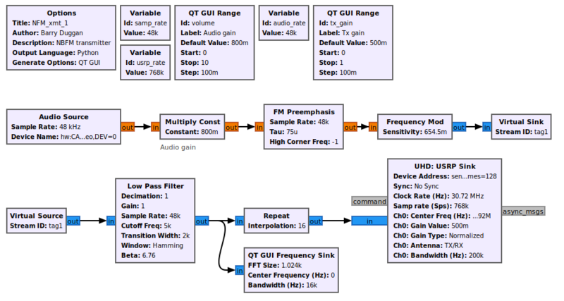
Example Flowgraph
Source Files
- Python files
- [1]
- Block definition
- [2]
