Throttle
Throttle flow of samples such that the average rate does not exceed the specific rate (in samples per second).
The throttle block copies the items from its input to its output, or just consumes the input samples at a specified average rate. It does not in any way change the digital signal.
A throttle block should be used only if your flowgraph includes no rate limiting block, which is typically hardware (e.g., an SDR, speaker, microphone). It is not intended nor effective at precisely controlling the rate of samples. If you need precise sample rates, the accuracy comes from an actual hardware sink or source, tied to an actual sample clock (USRPs, sound cards,…). GNU Radio itself does not care about "wall clock" time, and sees a signal as a "timeless" sequence of numbers. It operates on chunks of samples, on block, not on a per-sample basis, and not in a fixed rate.
The Throttle Block is typically attached directly to the output of a non-hardware source block (e.g. Signal Source), in order to limit the rate at which that source block creates samples.
Usage
The Throttle block has an optional output.
- Output connected
- If you use the Throttle "in line", i.e. in between a block that produces samples, and one that consumes samples, with both its input and its output connected, it will copy the input to the output. It does so in chunks of multiple samples, while waiting enough time before telling GNU Radio the samples are consumed on its input and produced on its output, to achieve the desired average rate of items per second.
- Output unconnected
- The Throttle will only consume chunks of items, at the specified average rate of items per second.
The second mode is the preferable – it doesn't occupy CPU or memory bandwidth for the mere act of copying data, whilst still limiting the rate of sample processing. Unless you know you want do a copy, it is functionally equivalent to put a Throttle block between two blocks A and B, and to put it "downstream" of A in parallel with B. The example below exemplifies this mode of operation.
Parameters
(R): Run-time adjustable
- Type
- Data type of the block can be complex, float, int, short or byte. Default value is complex.
- Sample rate(R)
- Maximum average sample rate desired.
- Vector length
- Default value = 1. Values > 1 allow for vectors of samples to be passed (for example, at the output of an FFT block)
- Ignore rx_rate tag
- If set to False, the block will set its sample rate to the value of recieved tags with the key rx_rate. It will ignore other tags.
- Limit
- "None", "Max Time (sec)", "Max items"
- To avoid maximally large chunks to be copied at maximally large latency (which can lead to very undesirable "laggy" behaviour in visual sinks), the maximum time that the block waits per copy can be specified (and thus, inherently the maximum number of samples that get copied at once), or the maximum number of items (and hence inherently the maximum time to wait between chunks).
- Maximum
- Time (float) or number of items (int)
- If the Limit Parameter was not set to "None", this sets the maximum for the limited latency or item chunk size.
Example Flowgraph
Demonstration
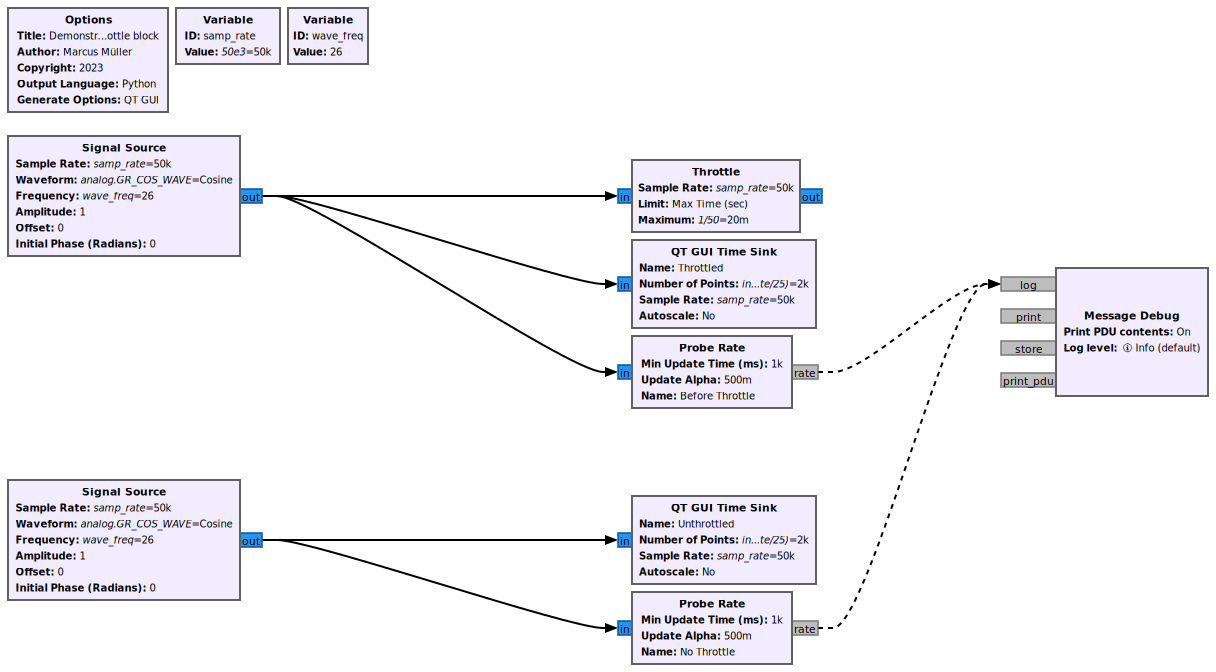
In the below flowgraph, the upper Signal Source is feeding into a Throttle block, which limits the rate at which it passes samples to 50,000 samples per second.
We use the "Limit" parameter to bound the maximum time that happens between a chunk of items being emitted by the Throttle block. We set that time to 1/50 of a second. (And that gives us 1/50 s · 50,000 Samples/s = 1000 Samples per chunk, at most.)
The lower Signal Source is not feeding into something that slows it down to a defined rate.
To test the rates at which samples pass through, we attach Probe Rate blocks, and give them distinct names. We use Message Debug to print these rates
We observe this:
- As we can see in the upper "Throttled" figure, the passing of samples of a defined rate leads to predictable displaying of the waveform. For the unthrottled data, not so much
- We observe the sample "passing through" rates before the Throttle: It is, on average, as expected, 50,000 per second.
- We observe the rate between the unthrottled Signal Source and the Sink: that is in the region of 288 million samples a second. It's purely random which part of the waveform we see.
- The upper Signal source consumes negligible amounts of CPU. The lower one fully consumes a CPU core, and hence leads to heat and noise from CPU coolers.
- It is especially noteworthy that throttling in the top part of the flow graph has no effect on the bottom part.
Source Files
- C++ files
- Here
- Header files
- Here
- Public header files
- Here
- Block definition
- Yaml

