Your First Flowgraph
This tutorial will guide you through creating and running your first flowgraph in GNURadio.
Starting GNURadio Companion
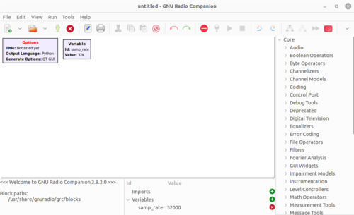
The GNURadio Companion (GRC) is a visual editor for assembling and flowgraphs. GRC uses .grc files which are then translated into Python .py flowgraphs. Start GRC by opening a terminal and typing:
$ gnuradio-companion &
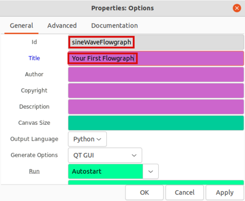
Double click the Options block on the upper left hand corner and name your flowgraph by editing the Id and Title entries:
The Id will be the filename of the Python flowgraph which in this case will be sineWaveFlowgraph.py. The Title entry is a description of the flowgraph. Click OK to save your changes.
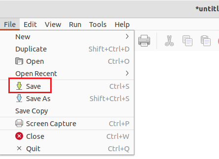
Click File : Save to save your GRC Flowgraph.
You will then need to enter a name for your .grc file which is sineWaveGRC.grc to distinguish it from the .py flowgraph.
Now that the GRC file is named and saved, blocks can be added to create your first flowgraph.
Adding Blocks
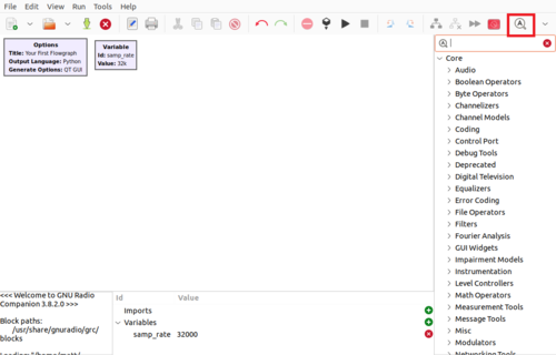
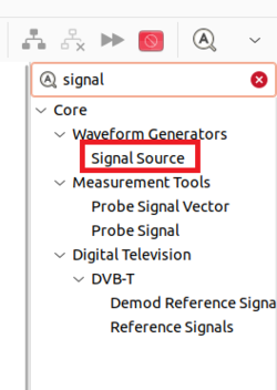
GNURadio comes with a large pre-existing library of signal processing blocks. The blocks can be browsed using the arrows in the right hand column, or you may search for blocks by using CTRL+F or by selecting the magnifying glass (highlighted in red):
Search for the Signal Source block and then drag and drop it into the GRC workspace:
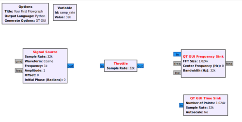
Now search for Throttle, QT GUI Frequency Sink and QT GUI Time Sink. Drag and drop each of the blocks into the workspace so the flowgraph looks like the following:
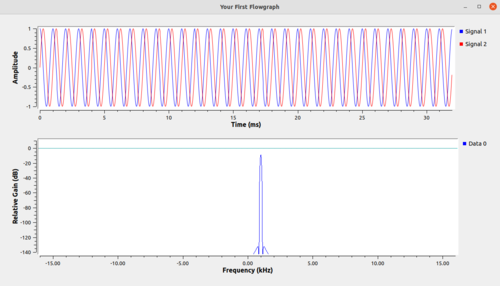
The Signal Source block will create a complex sinusoid, QT GUI Frequency Sink will display the magnitude of the frequency spectrum of the complex sinusoid and QT GUI Time Sink will display the time domain. The Throttle block is used for flow control in the absence of radio hardware.
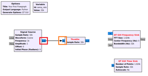
The blocks need to be connected. First click the output of Signal Source (highlighted in red) and then click the input to the Throttle (highlighted in orange).
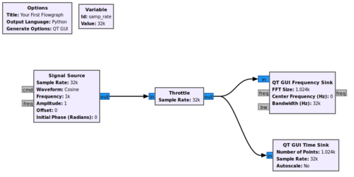
You will notice that the Signal Source block text has changed from red to black. The red text shows a user that a block still has an input or output that needs to be connected before the flowgraph can be run. Now connect the throttle output to the frequency sink and time sink:
Running The Flowgraph
Press the Play button (highlighted in red) to run the flowgraph:
A new window will pop-up displaying the signal in the time domain and frequency domain:
Success! Your flowgraph is now running.
