Selector: Difference between revisions
(add message ports) |
|||
| (2 intermediate revisions by 2 users not shown) | |||
| Line 22: | Line 22: | ||
; Output Index (''R'') | ; Output Index (''R'') | ||
: Used to choose which output stream gets the input copied to it. It is typical for this to be changed in realtime using e.g. a [[QT GUI Chooser]] | : Used to choose which output stream gets the input copied to it. It is typical for this to be changed in realtime using e.g. a [[QT GUI Chooser]] | ||
== Messages == | |||
; Enable | |||
: The 'en' message port accepts only <b>raw</b> PMT messages of the form <code>pmt.to_pmt(False)</code> or <code>pmt.to_pmt(True)</code> | |||
; Input index | |||
: The 'iindex' message port accepts only <b>raw</b> PMT messages of the form <code>pmt.from_long(index)</code> | |||
; Output index | |||
: The 'oindex' message port accepts only <b>raw</b> PMT messages of the form <code>pmt.from_long(index)</code> | |||
== Example Flowgraph == | == Example Flowgraph == | ||
This example flowgraph is located in [https://github.com/gnuradio/gnuradio/blob/master/gr-blocks/examples/selector.grc] | |||
[[File:Selector_example_flowgraph.png|800px]] | |||
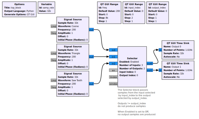
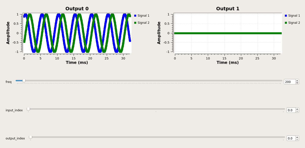
In this example, there are three input signals, which can be directed by the parameters of the selector block to one of two of the output ports. In the case where the input is set to 0 and the output is set to 0, we get the cosine signal passing from input 0 to Output 0. In this case Output 1 produces no samples. | |||
[[File:Selector_output_1.png]] | |||
If we change the output index to 1, and the input index to 1, we see the triangle wave produced at output 1. Output 0 in this case is producing no output samples, but the QT GUI Time sink does not update the display. | |||
[[File:Selector_output_2.png]] | |||
== Source Files == | == Source Files == | ||
; C++ files | ; C++ files | ||
: [https://github.com/gnuradio/gnuradio | : [https://github.com/gnuradio/gnuradio/blob/master/gr-blocks/lib/selector_impl.cc] | ||
; Header files | ; Header files | ||
: [https://github.com/gnuradio/gnuradio | : [https://github.com/gnuradio/gnuradio/blob/master/gr-blocks/lib/selector_impl.h] | ||
; Public header files | ; Public header files | ||
: [https://github.com/gnuradio/gnuradio | : [https://github.com/gnuradio/gnuradio/blob/master/gr-blocks/include/gnuradio/blocks/selector.h] | ||
; Block definition | ; Block definition | ||
: [https://github.com/gnuradio/gnuradio | : [https://github.com/gnuradio/gnuradio/blob/master/gr-blocks/grc/blocks_selector.block.yml] | ||
Revision as of 03:03, 22 December 2020
Connect the sink at input index to the source at output index. Samples from other input ports are consumed and dumped. Other output ports produce no samples.
output[output_index][i] = input[input_index][i]
Parameters
(R): Run-time adjustable
- Enabled (R)
- Whether or not input gets copied to output.
- NOTE: Selector block prior to GR 3.8 does not have Enabled parameter
- Number of Inputs
- Number of input streams
- Number of Outputs
- Number of output streams
- Input Index (R)
- Used to choose which input stream gets used. It is typical for this to be changed in realtime using e.g. a QT GUI Chooser
- Output Index (R)
- Used to choose which output stream gets the input copied to it. It is typical for this to be changed in realtime using e.g. a QT GUI Chooser
Messages
- Enable
- The 'en' message port accepts only raw PMT messages of the form
pmt.to_pmt(False)orpmt.to_pmt(True)
- Input index
- The 'iindex' message port accepts only raw PMT messages of the form
pmt.from_long(index)
- Output index
- The 'oindex' message port accepts only raw PMT messages of the form
pmt.from_long(index)
Example Flowgraph
This example flowgraph is located in [1]
In this example, there are three input signals, which can be directed by the parameters of the selector block to one of two of the output ports. In the case where the input is set to 0 and the output is set to 0, we get the cosine signal passing from input 0 to Output 0. In this case Output 1 produces no samples.
If we change the output index to 1, and the input index to 1, we see the triangle wave produced at output 1. Output 0 in this case is producing no output samples, but the QT GUI Time sink does not update the display.
Source Files
- C++ files
- [2]
- Header files
- [3]
- Public header files
- [4]
- Block definition
- [5]


