Symbol Sync: Difference between revisions
(Created page with "Symbol Sync is a type of symbol synchronizer that performs a bunch of tasks typically required to receive/decode a digital signal from over the air, listed below. This block...") |
m (Source links) |
||
| (20 intermediate revisions by 6 users not shown) | |||
| Line 1: | Line 1: | ||
Symbol Sync | [[Category:Block Docs]] | ||
[[File:symbol_sync_block.png|300px|right]] | |||
The '''Symbol Sync''' block performs clock recovery. It synchronizes to the symbols in a digital signal, extracting them and reducing them to their individual representations, such as a bit. This is often a critical final step in the demodulation process, as clock recovery reduces a stream of samples of symbols to raw 1s and 0s. This block is the successor to the [[Clock Recovery MM]] and MSK Timing Recovery blocks, which are now deprecated. | |||
The Symbol Sync block performs four main steps: | |||
[[File:symbol_sync_1.png|500px|right]] | |||
1. Estimates and tracks symbol rate (i.e. number of samples per symbol), given an initial estimate of samples per symbol and an allowable deviation from that estimate. | 1. Estimates and tracks symbol rate (i.e. number of samples per symbol), given an initial estimate of samples per symbol and an allowable deviation from that estimate. | ||
2. Performs the timing synchronization needed so that the signal is sampled at exactly the right moment in time, which is when each symbol/pulse is at its | 2. Performs the timing synchronization needed so that the signal is sampled at exactly the right moment in time, which is when each symbol/pulse is at its maximum value. | ||
3. Decimate the signal so that what comes out of the block is 1 sample per symbol (or multiple if the user would like, but it's usually set to 1 or sometimes 2). | |||
4. Filter the signal appropriately. | |||
In essence, the Symbol Sync block operates a loop, typically a sampling length of a symbol, and then adjusts this loop until it is properly aligned with each symbol in the series. | |||
For more information, see the [https://www.gnuradio.org/grcon/grcon17/presentations/symbol_clock_recovery_and_improved_symbol_synchronization_blocks/ GNU Radio Conference 2017 presentation] on this block (PDF slides and Video). Example flowgraphs using this block can be found [https://github.com/gnuradio/gnuradio/tree/main/gr-digital/examples/demod here] | |||
== Parameters == | |||
<b>(''R''):</b> <span class="plainlinks">[https://wiki.gnuradio.org/index.php/GNURadioCompanion#Variable_Controls ''Run-time adjustable'']</span> | |||
; Timing Error Detector (TED) | |||
: The type of timing error detector to use. See enum ted_type for a list of possible types. Each TED has different tactics for clock recovery and each TED may be useful in different scenarios. For example, the Early-Late TED locks onto a demodulated FSK signal very well. | |||
; Samples per Symbol (R) | |||
: User specified nominal clock period in samples per symbol. If this is not predetermined, it can be computed by dividing the sampling rate by the baud rate. | |||
; Expected TED Gain (R) | |||
: Expected gain of the timing error detector, given the TED in use and the anticipated input amplitude, pulse shape, and Es/No. This value is the slope of the TED's S-curve at timing offset tau = 0. This value is normally computed by the user analytically or by simulation in a tool outside of GNU Radio. This value must be correct for the loop filter gains to be computed properly from the desired input loop bandwidth and damping factor. This is the most sensitive analytical parameter. If you are unable to compute this, consider using a slider using the [[QT GUI Range]] widget to experiment on a good value. This number should be somewhere above 0 but likely less than 1. | |||
; Loop BW (R) | |||
[[ | : Approximate normalized loop bandwidth of the symbol clock tracking loop. It should nominally be close to 0, but greater than 0. If unsure, start with a number around 2*pi*0.04, and experiment to find the value that works best for your situation. This value can also be found experimentally using a [[QT GUI Range]] slider widget, likely somewhere in the range between 0 and 1. | ||
; Damping Factor (R) | |||
: Damping factor of the symbol clock tracking loop. Damping < 1.0 is an under-damped loop. Damping = 1.0/sqrt(2.0) is a maximally flat loop response. Damping = 1.0 is a critically-damped loop. Damping > 1.0 is an over-damped loop. Start with critically damped or over-damped. An under-damped loop is usually not desirable for timing recovery. The default is 1.0, which should work in general. | |||
; Max Deviation | |||
: Maximum absolute deviation of the average clock period estimate from the user specified nominal clock period in units of samples per symbol. Smaller is better for acquiring lock at start of burst. Too small misses data when symbol clock is far from nominal. The default is 1.5, which should work in most cases. | |||
Samples | ; Output Samples/Symbol | ||
: The number of output samples per symbol (default=1). Normally set to 1; or to 2 if upstream from an equalizer block. | |||
; TED Slicer Constellation | |||
: A constellation obj shared pointer that will be used by decision directed timing error detectors to make decisions. I.e. the timing error detector will use this constellation as a slicer, if the particular algorithm needs sliced symbols. | |||
; Interpolating Resampler Type | |||
: The enumerated type of interpolating resampler to use. See the interpolating resampler type enum for a list of possible types. | |||
; Num Filters (if using certain resamplers) | |||
: The number of arms in the polyphase filterbank of the interpolating resampler, if using an interpolating resampler that uses a PFB. | |||
; PFB Taps (if used certain resamplers) | |||
: The prototype filter for the polyphase filterbank of the interpolating resampler, if using an interpolating resampler that uses a PFB. | |||
== Example == | |||
In this example, the Symbol Sync is fed a demodulated Frequency-Shift Keying (FSK) signal and produces soft data bits. A [[Binary Slicer]] block can then be used to turn these into hard zeros or ones. | |||
<gallery mode="packed"> | |||
File:Symbol_Sync_flowgraph.png|The Symbol Sync block is fed a demodulated FSK signal that has been further enhanced by the Root Raised Cosine match filter. | |||
File:Symbol_Sync_example.png|The demodulated FSK signal forms square waves, which are refined into sinusoidal waves by the match filter. The Symbol Sync block locks onto each peak, producing pure bits with an error rate. Note that it takes Symbol Sync a while to fully sync; this is often the purpose of a long preamble. | |||
</gallery> | |||
[[File:Symbol_Sync_Recovery.png|right|thumb|400px|The Symbol Sync block performs swift synchronization with the right parameters.]] | |||
== Usage Hints and Gotchas == | |||
# Input signal should be at a consistent amplitude (e.g., ±1.0). This can be achieved with the [[Quadrature Demod]], [[Root Raised Cosine Filter]], or an Automatic Gain Control block. TEDs have specific assumptions about input amplitudes! | |||
# For decision directed TEDs (M&M, Modified M&M, Zero Crossing), the input signal amplitude should match constellation. Note that GNU Radio's Constellation Object silently scales your constellation! | |||
# Input signal should not have a DC offset. In other words, it must alternate between 0.0, not some other number. | |||
# Input signal should be peaked at symbol centers, except for MSK signals and MSK TEDs. This requirement will normally be accomplished by the matched filter, such as the Root Raised Cosine Filter, which occurs before the Symbol Sync block, unless you use the PFB, MF resampler which does the matched filtering for you. This is demonstrated in one of the above examples. | |||
== Block Diagram of Block == | |||
[[File:symbol_sync_2.png|600px]] | [[File:symbol_sync_2.png|600px]] | ||
== Source Files == | |||
; C++ files | |||
: [https://github.com/gnuradio/gnuradio/blob/main/gr-digital/lib/symbol_sync_cc_impl.cc symbol_sync_cc_impl.cc] [https://github.com/gnuradio/gnuradio/blob/main/gr-digital/lib/symbol_sync_ff_impl.cc symbol_sync_ff_impl.cc] | |||
; Header files | |||
: [https://github.com/gnuradio/gnuradio/blob/main/gr-digital/lib/symbol_sync_cc_impl.h symbol_sync_cc_impl.h] [https://github.com/gnuradio/gnuradio/blob/main/gr-digital/lib/symbol_sync_ff_impl.h symbol_sync_ff_impl.h] | |||
; Public header files | |||
: [https://github.com/gnuradio/gnuradio/blob/main/gr-digital/include/gnuradio/digital/symbol_sync_cc.h symbol_sync_cc.h] [https://github.com/gnuradio/gnuradio/blob/main/gr-digital/include/gnuradio/digital/symbol_sync_ff.h symbol_sync_ff.h] | |||
; Block definition | |||
: [https://github.com/gnuradio/gnuradio/blob/main/gr-digital/grc/digital_symbol_sync_xx.block.yml digital_symbol_sync_xx.block.yml] | |||
Latest revision as of 11:34, 19 April 2024

The Symbol Sync block performs clock recovery. It synchronizes to the symbols in a digital signal, extracting them and reducing them to their individual representations, such as a bit. This is often a critical final step in the demodulation process, as clock recovery reduces a stream of samples of symbols to raw 1s and 0s. This block is the successor to the Clock Recovery MM and MSK Timing Recovery blocks, which are now deprecated.
The Symbol Sync block performs four main steps:

1. Estimates and tracks symbol rate (i.e. number of samples per symbol), given an initial estimate of samples per symbol and an allowable deviation from that estimate.
2. Performs the timing synchronization needed so that the signal is sampled at exactly the right moment in time, which is when each symbol/pulse is at its maximum value.
3. Decimate the signal so that what comes out of the block is 1 sample per symbol (or multiple if the user would like, but it's usually set to 1 or sometimes 2).
4. Filter the signal appropriately.
In essence, the Symbol Sync block operates a loop, typically a sampling length of a symbol, and then adjusts this loop until it is properly aligned with each symbol in the series.
For more information, see the GNU Radio Conference 2017 presentation on this block (PDF slides and Video). Example flowgraphs using this block can be found here
Parameters
(R): Run-time adjustable
- Timing Error Detector (TED)
- The type of timing error detector to use. See enum ted_type for a list of possible types. Each TED has different tactics for clock recovery and each TED may be useful in different scenarios. For example, the Early-Late TED locks onto a demodulated FSK signal very well.
- Samples per Symbol (R)
- User specified nominal clock period in samples per symbol. If this is not predetermined, it can be computed by dividing the sampling rate by the baud rate.
- Expected TED Gain (R)
- Expected gain of the timing error detector, given the TED in use and the anticipated input amplitude, pulse shape, and Es/No. This value is the slope of the TED's S-curve at timing offset tau = 0. This value is normally computed by the user analytically or by simulation in a tool outside of GNU Radio. This value must be correct for the loop filter gains to be computed properly from the desired input loop bandwidth and damping factor. This is the most sensitive analytical parameter. If you are unable to compute this, consider using a slider using the QT GUI Range widget to experiment on a good value. This number should be somewhere above 0 but likely less than 1.
- Loop BW (R)
- Approximate normalized loop bandwidth of the symbol clock tracking loop. It should nominally be close to 0, but greater than 0. If unsure, start with a number around 2*pi*0.04, and experiment to find the value that works best for your situation. This value can also be found experimentally using a QT GUI Range slider widget, likely somewhere in the range between 0 and 1.
- Damping Factor (R)
- Damping factor of the symbol clock tracking loop. Damping < 1.0 is an under-damped loop. Damping = 1.0/sqrt(2.0) is a maximally flat loop response. Damping = 1.0 is a critically-damped loop. Damping > 1.0 is an over-damped loop. Start with critically damped or over-damped. An under-damped loop is usually not desirable for timing recovery. The default is 1.0, which should work in general.
- Max Deviation
- Maximum absolute deviation of the average clock period estimate from the user specified nominal clock period in units of samples per symbol. Smaller is better for acquiring lock at start of burst. Too small misses data when symbol clock is far from nominal. The default is 1.5, which should work in most cases.
- Output Samples/Symbol
- The number of output samples per symbol (default=1). Normally set to 1; or to 2 if upstream from an equalizer block.
- TED Slicer Constellation
- A constellation obj shared pointer that will be used by decision directed timing error detectors to make decisions. I.e. the timing error detector will use this constellation as a slicer, if the particular algorithm needs sliced symbols.
- Interpolating Resampler Type
- The enumerated type of interpolating resampler to use. See the interpolating resampler type enum for a list of possible types.
- Num Filters (if using certain resamplers)
- The number of arms in the polyphase filterbank of the interpolating resampler, if using an interpolating resampler that uses a PFB.
- PFB Taps (if used certain resamplers)
- The prototype filter for the polyphase filterbank of the interpolating resampler, if using an interpolating resampler that uses a PFB.
Example
In this example, the Symbol Sync is fed a demodulated Frequency-Shift Keying (FSK) signal and produces soft data bits. A Binary Slicer block can then be used to turn these into hard zeros or ones.
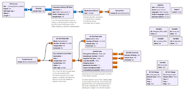
The Symbol Sync block is fed a demodulated FSK signal that has been further enhanced by the Root Raised Cosine match filter.
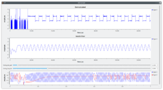
The demodulated FSK signal forms square waves, which are refined into sinusoidal waves by the match filter. The Symbol Sync block locks onto each peak, producing pure bits with an error rate. Note that it takes Symbol Sync a while to fully sync; this is often the purpose of a long preamble.


Usage Hints and Gotchas
- Input signal should be at a consistent amplitude (e.g., ±1.0). This can be achieved with the Quadrature Demod, Root Raised Cosine Filter, or an Automatic Gain Control block. TEDs have specific assumptions about input amplitudes!
- For decision directed TEDs (M&M, Modified M&M, Zero Crossing), the input signal amplitude should match constellation. Note that GNU Radio's Constellation Object silently scales your constellation!
- Input signal should not have a DC offset. In other words, it must alternate between 0.0, not some other number.
- Input signal should be peaked at symbol centers, except for MSK signals and MSK TEDs. This requirement will normally be accomplished by the matched filter, such as the Root Raised Cosine Filter, which occurs before the Symbol Sync block, unless you use the PFB, MF resampler which does the matched filtering for you. This is demonstrated in one of the above examples.
Block Diagram of Block

Source Files
- C++ files
- symbol_sync_cc_impl.cc symbol_sync_ff_impl.cc
- Header files
- symbol_sync_cc_impl.h symbol_sync_ff_impl.h
- Public header files
- symbol_sync_cc.h symbol_sync_ff.h
- Block definition
- digital_symbol_sync_xx.block.yml