Packet Communications Test Page: Difference between revisions
No edit summary |
No edit summary |
||
| Line 1: | Line 1: | ||
<span | <span id="gr_vad"></span> | ||
<hr> | |||
This tutorial presents methods to transmit and receive packet data using burst transmissions. The examples show data originating from a PDU message source. A hardware simulation is shown using BPSK modulation. | This tutorial presents methods to transmit and receive packet data using burst transmissions. The examples show data originating from a PDU message source. A hardware simulation is shown using BPSK modulation. | ||
Revision as of 22:58, 17 December 2022
This tutorial presents methods to transmit and receive packet data using burst transmissions. The examples show data originating from a PDU message source. A hardware simulation is shown using BPSK modulation.
Prerequisites
- QPSK Modulation / Demodulation
- BPSK Demodulation
- Polymorphic Types (PMTs)
- Stream Tags
- Message Passing
- Understanding ZMQ Blocks
- Packet Communications
Notes
The current tutorial has been revised and tested with GNU Radio version 3.9.4.0. The 'Polyphase Clock Sync' has been replaced with the Symbol_Sync; and the 'CMA Equalizer' has been replaced with the Linear_Equalizer and Adaptive_Algorithm.
Links to the flowgraphs have been updated to GNU Radio version 3.9.4.0.
If using GNURadio 3.8:
-In the "Simulating Baseband Packet Processing" Tutorial, "NOTE:" sections have been added where a small change is needed or a difference occurs.
-The "Using BPSK with Hardware Simulation" has an entirely separate section for version 3.8.
Simulating Baseband Packet Processing
In order to grasp the basics of packet processing, this section presents a transmitter and receiver simulation using standard GNU Radio blocks without any modulation or channel impairments. As was shown in the QPSK and BPSK tutorials, the received bit data stream could be verified by comparing it to the (delayed) transmitted data. However, there was no way to recover the byte alignment of those bits. That is where packet processing comes into play.
Building the flowgraph
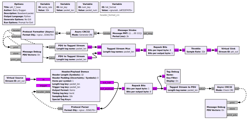
Build the following flowgraph using the details given below:
This flowgraph can be downloaded from Media:Pkt_7_base.grc.
NOTE: If using GNURadio 3.8, a small change will need to be made: Move the connections coming out of the 'header' and 'payload' ports on the async protocol formatter from the 'print' port of the Message Debug block to the 'print_pdu' port.
Message Strobe
For the Message Strobe to generate a PDU, the Message PMT must be of the form
pmt.cons(pmt.PMT_NIL,pmt.init_u8vector(9,(71,78,85,32,82,97,100,105,111)))
This specific vector has a length of 9 and the character values of "GNU Radio". It is sent every two seconds.
Async CRC32
The Async CRC32 block computes the CRC of the payload and appends the value to it.
Variable, Id: hdr_format
The Protocol Formatter uses a Format Object to define its parameters. The one used in this example is
hdr_format digital.header_format_crc(len_key, num_key)
It generates a header with the packet length, packet number, and a 16-bit CRC. No access code is created.
Protocol Formatter
The entry for the Format Obj. is 'hdr_format'
Tagged Stream Mux
The Tagged Stream Mux combines the header and the payload.
Header/Payload Demux
The Header/Payload Demux block synchronizes with the header data and then outputs the payload data.
Protocol Parser
The entry for the Format Obj. is 'hdr_format'
Testing
To test the flowgraph, click the "Execute the flowgraph" icon, or press F6. An example of the output is:
***** VERBOSE PDU DEBUG PRINT ******
()
pdu length = 4 bytes
pdu vector contents =
0000: 0d 10 00 3a
************************************
***** VERBOSE PDU DEBUG PRINT ******
()
pdu length = 13 bytes
pdu vector contents =
0000: 47 4e 55 20 52 61 64 69 6f 8f aa 09 f1
************************************

----------------------------------------------------------------------
Tag Debug:
Input Stream: 00
  Offset: 13  Source: n/a     Key: packet_len   Value: 13
  Offset: 13  Source: n/a     Key: packet_num   Value: 1
----------------------------------------------------------------------
***** VERBOSE PDU DEBUG PRINT ******
((packet_num . 1))
pdu length = 9 bytes
pdu vector contents =
0000: 47 4e 55 20 52 61 64 69 6f
************************************
The first PDU DEBUG PRINT is the header data containing the payload length, packet number, and a CRC8 of the header.
The second PDU DEBUG PRINT is the payload including a CRC32 of the data.
The Tag Debug shows the length tag and the packet number tag.
The third PDU DEBUG PRINT is the received payload ("GNU Radio").
NOTE: If using GNURadio 3.8, the output will differ in the VERBOSE PDU DEBUG PRINT section. Instead of the hexidecimal representation of "GNU Radio", the actual ASCII text "GNU Radio" will print in the termainal as shown below.
* MESSAGE DEBUG PRINT PDU VERBOSE *
()
pdu_length = 4
contents =
0000: 0d 10 00 3a
***********************************
* MESSAGE DEBUG PRINT PDU VERBOSE *
()
pdu_length = 13
contents =
0000: 47 4e 55 20 52 61 64 69 6f 8f aa 09 f1
***********************************

----------------------------------------------------------------------
Tag Debug:
Input Stream: 00
  Offset: 13  Source: n/a     Key: packet_len   Value: 13
  Offset: 13  Source: n/a     Key: packet_num   Value: 1
----------------------------------------------------------------------
******* MESSAGE DEBUG PRINT ********
(((packet_num . 1)) . #[G N U   R a d i o])
************************************
Using BPSK with Hardware Simulation (version 3.9)
The Protocol Formatter supports three header format types: default, count, and crc. The crc style is illustrated in the simulation above.
In order to create a preamble, a default header, and the payload data in one PDU message, an Embedded Python block was created. The code is contained in the GRC file, but also is shown here:
"""
Embedded Python Block
"""

import numpy as np
from gnuradio import gr
import pmt

class blk(gr.sync_block):
    """Packet Format"""

    def __init__(self):
        gr.sync_block.__init__(self,
            name = "Packet Format",
            in_sig = None,
            out_sig = None)
        self.message_port_register_in(pmt.intern('PDU_in'))
        self.message_port_register_out(pmt.intern('PDU_out'))
        self.set_msg_handler(pmt.intern('PDU_in'), self.handle_msg)

    def handle_msg(self, msg):
        inMsg = pmt.to_python (msg)
        pld = inMsg[1]
        # print (pld)
        mLen = len(pld)
        # print (mLen)
        if (mLen > 0):
            char_list = [85,85,85,85,85,85,85,85,85,85,85,85,85,85,85,85,85,85,85,85,85,85,85,85,85,85,85,85,85,85,85,85,225,90,232,147]
            char_list.append (mLen >> 8)
            char_list.append (mLen & 255)
            char_list.append (mLen >> 8)
            char_list.append (mLen & 255)
            char_list.extend (pld)
            # print (char_list)
            out_len = len(char_list)
            # print (out_len)
            self.message_port_pub(pmt.intern('PDU_out'), pmt.cons(pmt.PMT_NIL,pmt.init_u8vector(out_len,(char_list))))
The preamble is 32 bytes of 0x55 giving alternating 1's and 0's. The non-cyclical 32-bit access code is 0xe15ae893 (binary '11100001010110101110100010010011'). The length of the payload is repeated (16 bits). Then the payload is appended.
Transmitting a Signal
Build the following flowgraph using the details given below:
This flowgraph can be downloaded from Media:Pkt_xmt.grc. The BPSK modulation is done in the same manner as the BPSK Demodulation tutorial. Do a Generate (F5) or Execute (F6) to create the pkt_xmt.py file.
Receiving a Signal
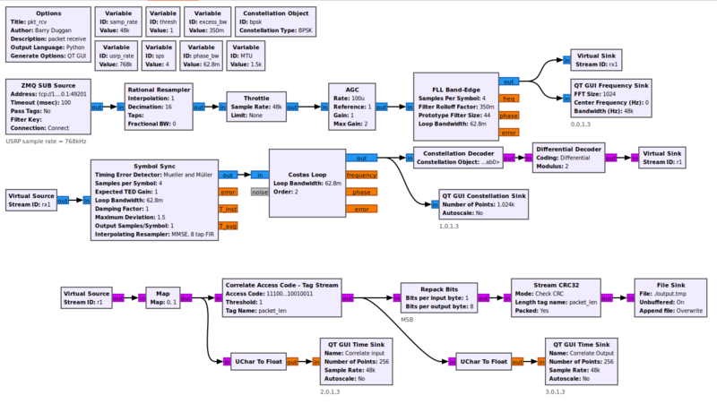
Build a separate flowgraph using the details below:
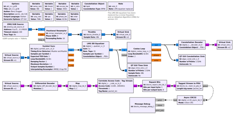
This flowgraph can be downloaded from Media:Pkt_rcv.grc. For GNU Radio version 3.9 there are two changes: the Polyphase Clock Sync has been replaced by the Symbol_Sync block; and the CMA equalizer has been replaced by a Linear Equalizer and an Adaptive Algorithm.
The output of the Map block is the received bit stream. The 'Correlate Access Code - Tag Stream' block searches for the given access code by slicing the soft decision symbol inputs. Once found, it expects the following 32 samples to contain a header that includes the frame length (16 bits for the length, repeated). It decodes the header to get the frame length in order to set up the the tagged stream key information.
The remaining blocks operate as in the simulation example above.
Testing
When using GRC, doing a Generate and/or Run creates a Python file with the same name as the .grc file. You can execute the Python file without running GRC again.
For testing this system we will use two processes, so we will need two terminal windows.
Terminal 1:
- since you just finished building the pkt_rcv flowgraph, you can just do a Run. After a few seconds, a window will open with the GUI Constellation Sink.
Terminal 2: Open another terminal window.
- change to whatever directory you used to generate the flowgraph for pkt_xmt
- execute the following command:
python3 pkt_xmt.py
- After a few seconds, a window will open with the GUI Time Sink.
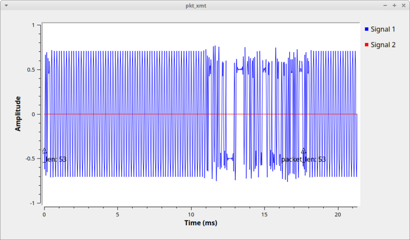
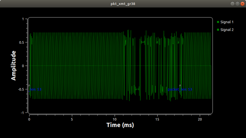
The output of the transmitter is:
The output of the receiver is shown on the GRC console.
***** VERBOSE PDU DEBUG PRINT ******
()
pdu length = 9 bytes
pdu vector contents =
0000: 47 4e 55 20 52 61 64 69 6f
************************************
The PDU DEBUG PRINT is the received payload ("GNU Radio").
To terminate each of the processes cleanly, click on the 'X' in the upper corner of the GUI rather than using Control-C.
Using BPSK with Hardware Simulation (version 3.8)
The Protocol Formatter supports three header format types: default, count, and crc. The crc style is illustrated in the simulation above.
In order to create a preamble, a default header, and the payload data in one PDU message, an Embedded Python block was created. The code is contained in the GRC file, but also is shown here:
- note that for GNURadio 3.8 a numpy array is used in the handling of the incoming PMT message. It must also be put into a byte array before being placed into the PMT u8vector for publishing to the "PDU_out" port
"""
Embedded Python Block
"""

import numpy as np
from gnuradio import gr
import pmt
import array
class blk(gr.sync_block):
    """Packet Format"""

    def __init__(self):
        gr.sync_block.__init__(self,
            name = "Packet Format GR38",
            in_sig = None,
            out_sig = None)
        self.message_port_register_in(pmt.intern('PDU_in'))
        self.message_port_register_out(pmt.intern('PDU_out0'))
        self.set_msg_handler(pmt.intern('PDU_in'), self.handle_msg)

    def handle_msg(self, msg):
        inMsg = pmt.to_python (msg)
        pld = inMsg[1] ## type-> numpy.ndarray
        mLen = len(pld)
        if (mLen > 0):
            ## create a numpy array of type 'int' with preamble and sync word
            tmp_char_list = np.array([85,85,85,85,85,85,85,85,85,85,85,85,85,85,85,85,85,85,85,85,85,85,85,85,85,85,85,85,85,85,85,85,225,90,232,147],dtype=int)
            ## append length 2x
            tmp_char_list=np.append(tmp_char_list,(mLen >> 8))
            tmp_char_list=np.append(tmp_char_list,(mLen & 255))
            tmp_char_list=np.append(tmp_char_list,(mLen >> 8))
            tmp_char_list=np.append(tmp_char_list,(mLen & 255))
            tmp_char_list_len=len(tmp_char_list)
            ## append original payload
            new_char_list=np.insert(tmp_char_list,tmp_char_list_len,pld)
            new_char_list_len=len(new_char_list)
            ## save final numpy array as byte array, this requires 'import array'
            ## (many thanks to Francis A. for finding this fix)
            byte_array_new_char_list=array.array('B',new_char_list)
            new_bytes_out_len = len(byte_array_new_char_list)
            ## create PMT u8vector using byte array
            new_out_bytes_pmt=pmt.cons(pmt.PMT_NIL,pmt.init_u8vector(new_bytes_out_len,(byte_array_new_char_list)))
            self.message_port_pub(pmt.intern('PDU_out0'), new_out_bytes_pmt)
Transmitting a Signal
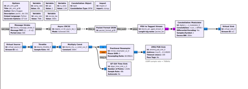
Build the following flowgraph using the details given below:
This flowgraph can be downloaded from Media:Pkt_xmt_gr38.grc. The BPSK modulation is done in the same manner as the BPSK Demodulation tutorial. Do a Generate (F5) or Execute (F6) to create the pkt_xmt_gr38.py file.
Receiving a Signal
Build a separate flowgraph using the details below:
- note for GNURadio 3.8: the Linear Equalizer shown in the GNURadio 3.9 example is not available. The LMS DD Equalizer has been used instead.
This flowgraph can be downloaded from Media:Pkt_rcv_gr38.grc. For GNU Radio version 3.8 there is one difference:the Linear Equalizer and Adaptive Algorithm object are not available, the LMS DD Equalizer block is used instead.
The output of the Map block is the received bit stream. The 'Correlate Access Code - Tag Stream' block searches for the given access code by slicing the soft decision symbol inputs. Once found, it expects the following 32 samples to contain a header that includes the frame length (16 bits for the length, repeated). It decodes the header to get the frame length in order to set up the the tagged stream key information.
The remaining blocks operate as in the simulation example above.
Testing
When using GRC, doing a Generate and/or Run creates a Python file with the same name as the .grc file. You can execute the Python file without running GRC again.
For testing this system we will use two processes, so we will need two terminal windows.
Terminal 1:
- since you just finished building the pkt_rcv_gr38 flowgraph, you can just do a Run. After a few seconds, a window will open with the GUI Constellation Sink.
Terminal 2: Open another terminal window.
- change to whatever directory you used to generate the flowgraph for pkt_xmt_gr38
- execute the following command:
python3 pkt_xmt_gr38.py
- After a few seconds, a window will open with the GUI Time Sink.
The output of the transmitter is:
The output of the receiver is shown on the GRC console.
******* MESSAGE DEBUG PRINT ********
(() . #[G N U   R a d i o])
************************************
******* MESSAGE DEBUG PRINT ********
(() . #[G N U   R a d i o])
************************************
******* MESSAGE DEBUG PRINT ********
(() . #[G N U   R a d i o])
************************************
The MESSAGE DEBUG PRINT is the received payload ("GNU Radio").
To terminate each of the processes cleanly, click on the 'X' in the upper corner of the GUI rather than using Control-C.
Adding Channel Impairments
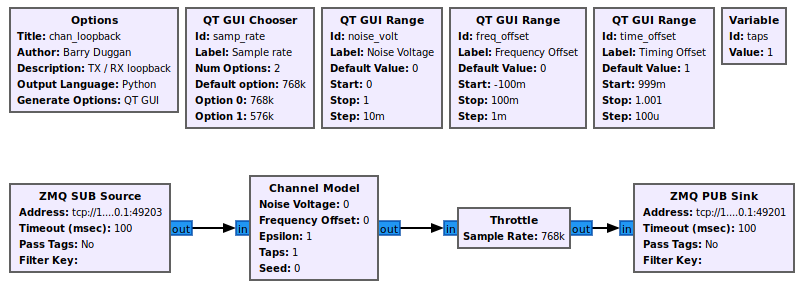
NOTE: For the testing above, the transmitter data on port 49203 was fed directly into the receiver on port 49203. In this section, we will insert another flowgraph between those two ZMQ ports, so the ZMQ SUB Source port in the receiver needs to be changed to 49201 and the flowgraph regenerated.
Build the following flowgraph:
This flowgraph can be downloaded from Media:Chan_loopback.grc.
For testing this arrangement we will use three processes, so we will need three terminal windows.
Terminal 1:
- since you just finished building the chan_loopback flowgraph, you can just do a Run. After a few seconds, a window will open with GUI Range controls for noise level, frequency offset, and timing offset.
Terminal 2: Open another terminal window.
- change to whatever directory you used to generate the flowgraph for pkt_xmt
- execute the following command:
python3 pkt_xmt.py
- After a few seconds, a window will open with the GUI Time Sink.
Terminal 3: Open another terminal window.
- change to whatever directory you used to generate the flowgraph for pkt_rcv
- execute the following command:
python3 pkt_rcv.py
- After a few seconds, a window will open with the GUI Constellation Sink.
Now you can adjust the various channel impairments to see the effect on the received constellation and the ability to synchronize on the received data. The sample rate should be set to 768kHz.
To terminate each of the processes cleanly, click on the 'X' in the upper corner of the GUI rather than using Control-C.
Using Hardware
If you look at https://github.com/duggabe/gr-control you will see that this tutorial follows the same design. If the user were to build two computer installations with this setup, they could send and receive packets.
Conclusions
Based on this tutorial, there are several things which can be concluded:
- BPSK and QPSK are not well suited for burst transmissions due to the need for the receiver to converge on the actual timing and frequency values.
- The longer the times between bursts of data, the more the receiver will need to reconverge on the timing and frequency values for the new burst.
- Since almost all amateur radio communications are half duplex and bursts of data, a more appropriate modulation would be FSK or AFSK. The same packet formatting and recovery would still apply. A proof of concept has been added to https://github.com/duggabe/gr-control with
pkt_fsk_xmt.grcandpkt_fsk_rcv.grc.
Further Observations
During the development and testing for this tutorial, the following items were observed:
- The 'Header/Payload Demux' and 'Protocol Parser' blocks seem to work only with the 'digital.header_format_crc' format.
- The 'Correlate Access Code - Tag Stream' block seems to require the Default Header Format Obj. and expects a 32-bit access code.
