QPSK Mod and Demod: Difference between revisions
| (17 intermediate revisions by 2 users not shown) | |||
| Line 1: | Line 1: | ||
This tutorial updates and replaces the [[Guided Tutorial PSK Demodulation]]. | |||
== Introduction == | == Introduction == | ||
| Line 24: | Line 23: | ||
This tutorial has been revised and tested with GNU Radio version 3.10.8.0. It strives to provide consistent flowgraphs where each stage builds on the previous one, maintaining the same parameters from one stage to the next. | This tutorial has been revised and tested with GNU Radio version 3.10.8.0. It strives to provide consistent flowgraphs where each stage builds on the previous one, maintaining the same parameters from one stage to the next. | ||
It is intended that the reader study the flowgraphs and resulting output, but not necessarily build each one. However, links to GRC source files are included. | It is intended that the reader study the flowgraphs and resulting output, but not necessarily build each one. However, links to GRC source files are included. Clicking the link of a '.grc' file will cause it to be downloaded. That file then can be opened by gnuradio-companion. | ||
=== Background === | |||
QPSK (Quadrature Phase Shift Keying) is a modulation technique where two bits are mapped into four symbols. Each symbol represents a phase shift in the carrier signal. A plot of the passband signal is shown below: | |||
[[File:Qpsk-passband.png|600px]] | |||
This diagram shows four phase shifts of the carrier at the start of each second. By coincidence, the phase transitions at t=1 and t=3 appear more subtle than the phase transition at t=2. Nevertheless, we observe phase transitions whenever a different symbol is transmitted. In a more realistic plot, the carrier frequency would be far higher than 3 Hz as shown in this diagram. | |||
Next is the complex baseband representation of the signal: | |||
[[File:Qpsk-baseband.png|600px]] | |||
The plot in red shows the phase of the complex baseband signal. As seen, the phase changes every second, representing a new symbol. | |||
A plot of the magnitude is shown as blue dots. For a rectangular pulse, all symbols have the same magnitude. | |||
Finally, the four symbols can be shown in a constellation plot: | |||
[[File:Qpsk-constel.png|400px]] | |||
Here, a complex Cartesian plot is shown for each symbol. From the origin, the points have an angle of 45, 135, 225, and 315 degrees. These phases are the most common way to transmit QPSK. Each point lies in a quadrant, and symbol decisions can be made by examining the sign of the real and imaginary component of the received symbol. | |||
== Transmitting a QPSK Signal == | == Transmitting a QPSK Signal == | ||
The first stage is transmitting the QPSK signal. We generate a stream of bits and modulate it onto a complex constellation. To do this, we use | The first stage is transmitting the QPSK signal. We generate a stream of bits and modulate it onto a complex constellation. To do this, we use a Constellation Object and [[Constellation_Modulator|Constellation Modulator]] block to control the transmitted signal. | ||
===Constellation Object=== | |||
GNU Radio provides a constellation object to aid in modulation and demodulation. In GRC, two blocks are available to create the constellation object. They are the Constellation Rect. Object and Constellation Object. | |||
====GRC Constellation Rect. Object==== | |||
The [[Constellation_Rect._Object|Constellation Rect. Object]] block is the preferred way to create a QPSK constellation. This block takes advantage of the rectangular shape of QPSK and allows fast decisions during demodulation. Furthermore, it provides automatic amplitude normalization for suitable use with hardware. The default parameters of this block provide an excellent QPSK model. | |||
[[File:Const_rect_properties.png|500px]] | |||
The ID parameter references the name of the object, and it is important to other GRC blocks that use it. This parameter should be changed to something memorable, and for this tutorial we use ''qpsk''. | |||
Two important parameters for transmission are Constellation Points and Symbol Map. | |||
Constellation Points is a list for each point in the complex plane. For the above constellation, the points start at the third quadrant (-1 - j) and move clockwise to the fourth quadrant (1 - j). This ordering is needed for differential encoding, which assumes the constellation points are listed clockwise or counterclockwise. The Const Rect. Object automatically scales these points to unit amplitude. | |||
When dealing with the number of samples per symbol, we want to keep this value as small as possible (minimum value of 2). Generally, we can use this value to help us match the desired bit rate with the sample rate of a hardware device. But since we're using simulation, the samples per symbol is only important in making sure we match this rate throughout the flowgraph. We'll use 4 here, which is greater than what we need, but useful to visualize the signal in the different domains. | The Symbol Map expresses the desired coding from input bits to the index of Constellation Points. The Symbol Map [0, 1, 3, 2] implements Gray coding. This coding ensures that the nearest neighbors only contain one bit difference. | ||
With proper use of a Map block, the two-bit input appears in the constellation as shown: | |||
01 | 11 | |||
---+--- | |||
00 | 10 | |||
If no symbol mapping is desired, Symbol Map may be set to [0, 1, 2, 3]. | |||
The other parameters in the Constellation Rect. Object are used for soft and hard decisions. Their default values should be left unchanged. | |||
====GRC Constellation Object==== | |||
The [[Constellation_Object|Constellation Object]] block also creates constellation objects including QPSK. The default parameters are very similar to the Constellation Rect. Object. However, the bit decision algorithm is less efficient. The Constellation Object block also contains hard-coded constellations under the Constellation Type parameter. They include DQPSK and QPSK. | |||
The DQPSK constellation begins in the first quadrant and rotates counter-clockwise. It allows Gray coding and differential encoding. Each point has a magnitude of 2 and therefore the output may need to be scaled when using hardware. Otherwise, it is a flexible and suitable constellation. | |||
The QPSK constellation has Gray coding automatically indexed in the constellation points. This indexing prevents the need for the Map block, but it also prevents differential encoding. There are additional subtleties in this block. For these reasons, ''we discourage beginners from using the hardcoded QPSK in the Constellation Object Block.'' | |||
====Methods==== | |||
Once the constellation object is created, there are many useful methods. We list the following of particular significance: | |||
* points() – The list of constellation points. These values may be normalized depending on how the object was created. | |||
* pre_diff_code() – The symbol mapping. The method name hints that symbol mapping should occur before differential encoding. | |||
* bits_per_symbol() – Bits per symbol; 2 for QPSK | |||
* arity() – The number of points in the constellation; 4 for QPSK | |||
===Constellation Modulator=== | |||
The [[Constellation_Modulator|Constellation Modulator]] is a hierarchical block that performs generic modulation for any constellation object. It takes packed bytes as inputs and produces complex RRC-filtered modulated samples as outputs. Because the constellation modulator expects packed bytes, we use a Random Source Generator to provide bytes with values of 0 to 255. | |||
The Constellation Modulator contains the following blocks: | |||
* [[Packed_to_Unpacked|Packed to Unpacked]] – unpack bytes to the constellation's bits per symbol | |||
* [[Map|Map]] – perform symbol mapping if applicable | |||
* [[Differential_Encoder|Differential Encoder]] – perform differential encoding if applicable | |||
* [[Chunks_to_Symbols|Chunks to Symbols]] – converts encoded bits to symbols in complex plane | |||
* [[Polyphase_Arbitrary_Resampler|Polyphase Arbitrary Resampler]] – performs RRC filtering at desired samples per symbol | |||
The Constellation Modulator block appears as follows: | |||
[[File:Constellation_modulator_block.png|200px]] | |||
The Constellation parameter is the ID of the Constellation Rect. Object (qpsk), even though it shows on the flowgraph as something else. | |||
The Differential Encoding parameter determines whether or not to apply this encoding. Differential encoding allows transmission based on the relative phase transitions between symbols. It makes demodulation easier by avoiding the challenges of absolute phase recovery caused by phase offsets and ambiguities between the transmitter and receiver. For many cases, however, the relative phase change between symbols remains consistent. Therefore, differential encoding simplifies demodulation at the cost of higher bit error rates. For these reasons, we use differential encoding in this tutorial to make demodulation less complex. For differential encoding and decoding to work with the default GNU Radio blocks, the points in the constellation object must be in clockwise or counterclockwise order. | |||
Samples/Symbol determines the samples per symbol. When dealing with the number of samples per symbol, we want to keep this value as small as possible (minimum value of 2). Generally, we can use this value to help us match the desired bit rate with the sample rate of a hardware device. But since we're using simulation, the samples per symbol is only important in making sure we match this rate throughout the flowgraph. We'll use 4 here, which is greater than what we need, but useful to visualize the signal in the different domains. | |||
More details regarding the Excess Bandwidth parameter are given below. | |||
=== Excess Bandwidth === | === Excess Bandwidth === | ||
| Line 79: | Line 174: | ||
=== Polyphase Clock Sync === | === Polyphase Clock Sync === | ||
The Polyphase Clock Sync provides three functions. First, it performs the clock recovery. Second, it provides the receiver matched filter to remove the ISI. Third, it down-samples the signal (reduces the samples per symbol). | |||
The example flowgraph [[Media:Qpsk_stage3.grc]] takes the output of the channel model and passes it through a Polyphase Clock Sync block. This block is setup with 32 filters and a loop bandwidth of 2pi/100. The block also takes in a value for the expected samples per symbol. | |||
[[File:Qpsk_stage3_fg.png|800px]] | |||
[[File:Qpsk_stage3_out.png|800px]] | |||
When running this script, we see the constellation is still a little noisy as a result of the ISI after the 32 filters, but is quickly absorbed by noise once we adjust the channel Noise Voltage setting to be more than 0. | |||
=== Multipath === | === Multipath === | ||
Multipath results from that fact that in most communication environments, we don't have a single path for the signal to travel from the transmitter to the receiver. Like the drawing below shows, any time there is an object that is reflective to the signal, a new path can be established between the two nodes. Surfaces like buildings, signs, trees, people, etc. can all produce signal reflections. Each of these reflective paths will show up at the receiver at different times based on the length of the path. Summing these together at the receiver causes distortions, both constructively and destructively. | |||
[[File:Multipath_cartoon.png|Multipath drawing]] | |||
=== Equalizer === | === Equalizer === | ||
The Adaptive Algorithm has a CMA algorithm type, or Constant Modulus Algorithm. It is a [http://en.wikipedia.org/wiki/Blind_equalization blind equalizer], but it only works on signals that have a constant amplitude, or modulus. This means that digital signals like QPSK are good candidates since they have points only on the unit circle. The [[Media:Qpsk_stage4.grc]] flowgraph illustrates this point. | |||
[[File:Qpsk_stage4_fg.png|800px]] | |||
We can watch the CMA algorithm converge. Note, too, that since we have both a clock sync and equalizer block, they are converging independently, but the one stage will affect the next stage. So there is some interaction going on here while both are locking on to the signal. In the end, though, we can see the effect of the time-locked multipath signal before and after the equalizer. Before the equalizer, we have a very ugly signal, even without noise. The equalizer nicely figures out how to invert and cancel out this channel so that we have a nice, clean signal again. We can also see the channel itself and how it flattens out nicely after the equalizer. | |||
[[File:Qpsk_stage4_out.png|800px]] | |||
=== Phase and Frequency Correction === | === Phase and Frequency Correction === | ||
Given that we've equalized the channel, we still have a problem of phase and frequency offset. Equalizers tend not to adapt quickly, and so a frequency offset easily can be beyond the ability of the equalizer to keep up. Also, if we're just running the CMA equalizer, all it cares about is converging to the unit circle. It has no knowledge of the constellation, so when it locks, it will lock at any given phase. We now need to correct for any phase offset as well as any frequency offset. | |||
Two things about this stage. First, we'll use a second order loop so that we can track both phase and frequency (which is the derivative of the phase) over time. Second, the type of recovery we'll deal with here assumes that we are doing ''fine'' frequency correction. So we must be sure that we are already within a decent range of the ideal frequency. If we are too far away, our loop here won't converge and we'll continue to spin. There are ways to do coarse frequency correction, such as the [[FLL_Band-Edge]] block, but we won't get getting into those here. | |||
For this task, we're going to use the [[Costas Loop]] in example [[Media:Qpsk_stage5.grc]]. The Costas Loop block can synchronize BPSK, QPSK, and 8PSK. Like all of our others, it uses a second order loop and is therefore defined with a loop bandwidth parameter. The other thing it needs to know is the order of the PSK modulation, so 2 for BPSK, 4 for QPSK, and 8 for 8PSK. | |||
[[File:Qpsk_stage5_fg.png|800px]] | |||
After the equalizer, the symbols are all on the unit circle, but rotating due to the frequency offset. At the output of the Costas loop block, we can see the locked constellation like we started with (plus the extra noise). | |||
[[File:Qpsk_stage5_out.png|800px]] | |||
=== Decoding === | === Decoding === | ||
[[Media:Qpsk_stage6.grc]] contains our final flowgraph to decode the signal. First, we insert a [[Constellation_Decoder|Constellation Decoder]] after the Costas loop, but our work is not quite done. At this point, we get our symbols from 0 to 3 because this is the size of our alphabet in a QPSK scheme. But, of those 0-3 symbols, how do we know for sure that we have the same mapping of symbols to constellation points that we did when we transmitted? Notice in our discussion above that nothing we did had any knowledge of the transmitted symbol-to-constellation mapping, which means we might have an ambiguity of 90 degrees in the constellation. Luckily, we avoided this problem by transmitting [http://en.wikipedia.org/wiki/Differential_coding ''differential'' symbols]. We didn't actually transmit the constellation itself, we transmitted the difference between symbols of the constellation by setting the Differential setting in the Constellation Modulator block to True. | |||
[[File:Qpsk_stage6_fg.png|800px]] | |||
The flowgraph uses the [[Differential_Decoder|Differential Decoder]] to translate the differential coded symbols back to their original symbols due to the phase transitions, not the absolute phase itself. But even out of here, our symbols are not exactly right. This is the hardest part about demodulation. In the synchronization steps, we had basic physics and math on our side. Now, though, we have to interpret some symbol based on what someone else said it was. Basically we just have to know this mapping. And luckily we do, so we use the [[Map|Map]] block to convert the symbols from the differential decoder to the original symbols we transmitted. At this point, we now have the original symbols from 0-3, so lets unpack those 2 bits per symbol into bits using the [[Unpack_K_Bits|unpack bits]] block. Now we have the original bit stream of data! | |||
But how do we know that it's the original bit stream? We'll compare the received stream to the input stream, which we can do because this is a simulation and we have access to the transmitted data. But of course, the transmitter produced ''packed bits'', so we again use the unpack bit block to unpack from 8-bits per byte to 1-bit per byte. We then convert these streams to floating point values of 0.0 and 1.0 simply because our time sinks only accept float and complex values. Comparing these two directly would show us... nothing. Why? Because the receiver chain has many blocks and filters that delay the signal, so the received signal is some number of bits behind. To compensate, we have to delay the transmit bits by the same amount using the [[Delay|Delay]] block. You can then adjust the delay to find the correct value and see how the bits synchronize. Note: wait a few seconds after each change of the delay value. Hint: the correct value is 58. | |||
[[File:Qpsk_stage6_out.png|800px]] | |||
[[Media:QPSK.grc]] contains a version that permits calculating the correct delay whose value is : int(5.5 * sps + 7)*2. Thus even for a different sps value, the delay will be automatically adjusted. | |||
[[File:QPSK.png|800px]] | |||
=== Using the Symbol Sync block === | |||
The [[Polyphase_Clock_Sync]] block will be deprecated in a future GNU Radio version (after v3.10.9.0). The replacement for it is a [[Symbol_Sync]] block. There is a good explanation of how the [[Symbol_Sync|Symbol Sync]] block works in the block documentation, including a link to a GRCon17 presentation about it. | |||
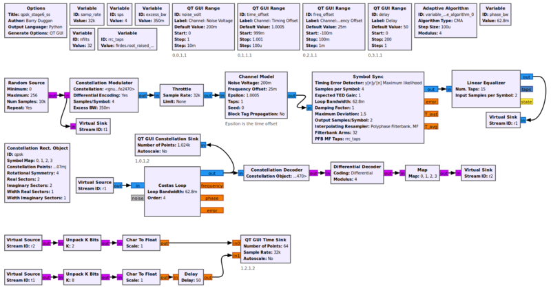
The stage6 source code using the Symbol Sync block is [[Media:Qpsk_stage6_ss.grc|here]]. The flowgraph is shown below. | |||
[[File:Qpsk_stage6_ss_fg.png|800px]] | |||
[[Category:Tested With 3.10]] | |||
Latest revision as of 13:37, 13 September 2025
This tutorial updates and replaces the Guided Tutorial PSK Demodulation.
Introduction
Objectives
- Understand issues of signal distortion and channel effects.
- Recognize the stages required to transmit and receive QPSK signals.
Prerequisites
The student should study each of the sections under the "Flowgraph Fundamentals" heading in Tutorials before attempting to do this tutorial.
References
- The ARRL Handbook, "Quadrature Modulation" section (any recent edition)
- f. j. harris and M. Rice, "Multirate Digital Filters for Symbol Timing Synchronization in Software Defined Radios", IEEE Selected Areas in Communications, Vol. 19, No. 12, Dec., 2001. [1]
- J. Feigin, "Practical Costas loop design: Designing a simple and inexpensive BPSK Costas loop carrier recovery circuit," RF signal processing, pp. 20-36, 2002
- Our Suggested Reading list
Notes
This tutorial has been revised and tested with GNU Radio version 3.10.8.0. It strives to provide consistent flowgraphs where each stage builds on the previous one, maintaining the same parameters from one stage to the next.
It is intended that the reader study the flowgraphs and resulting output, but not necessarily build each one. However, links to GRC source files are included. Clicking the link of a '.grc' file will cause it to be downloaded. That file then can be opened by gnuradio-companion.
Background
QPSK (Quadrature Phase Shift Keying) is a modulation technique where two bits are mapped into four symbols. Each symbol represents a phase shift in the carrier signal. A plot of the passband signal is shown below:
This diagram shows four phase shifts of the carrier at the start of each second. By coincidence, the phase transitions at t=1 and t=3 appear more subtle than the phase transition at t=2. Nevertheless, we observe phase transitions whenever a different symbol is transmitted. In a more realistic plot, the carrier frequency would be far higher than 3 Hz as shown in this diagram.
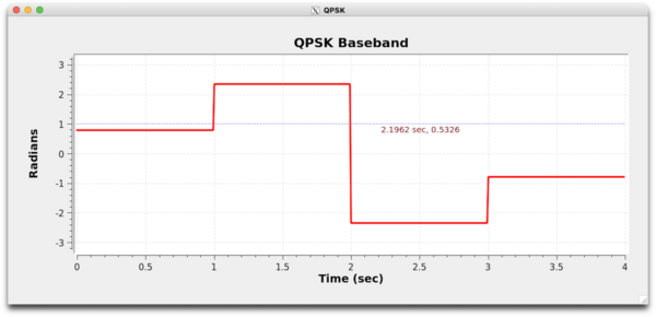
Next is the complex baseband representation of the signal:
The plot in red shows the phase of the complex baseband signal. As seen, the phase changes every second, representing a new symbol.
A plot of the magnitude is shown as blue dots. For a rectangular pulse, all symbols have the same magnitude.
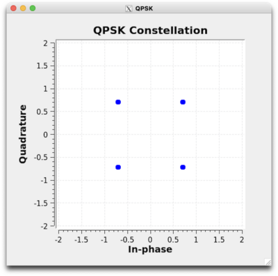
Finally, the four symbols can be shown in a constellation plot:
Here, a complex Cartesian plot is shown for each symbol. From the origin, the points have an angle of 45, 135, 225, and 315 degrees. These phases are the most common way to transmit QPSK. Each point lies in a quadrant, and symbol decisions can be made by examining the sign of the real and imaginary component of the received symbol.
Transmitting a QPSK Signal
The first stage is transmitting the QPSK signal. We generate a stream of bits and modulate it onto a complex constellation. To do this, we use a Constellation Object and Constellation Modulator block to control the transmitted signal.
Constellation Object
GNU Radio provides a constellation object to aid in modulation and demodulation. In GRC, two blocks are available to create the constellation object. They are the Constellation Rect. Object and Constellation Object.
GRC Constellation Rect. Object
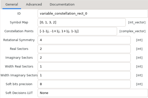
The Constellation Rect. Object block is the preferred way to create a QPSK constellation. This block takes advantage of the rectangular shape of QPSK and allows fast decisions during demodulation. Furthermore, it provides automatic amplitude normalization for suitable use with hardware. The default parameters of this block provide an excellent QPSK model.
The ID parameter references the name of the object, and it is important to other GRC blocks that use it. This parameter should be changed to something memorable, and for this tutorial we use qpsk.
Two important parameters for transmission are Constellation Points and Symbol Map.
Constellation Points is a list for each point in the complex plane. For the above constellation, the points start at the third quadrant (-1 - j) and move clockwise to the fourth quadrant (1 - j). This ordering is needed for differential encoding, which assumes the constellation points are listed clockwise or counterclockwise. The Const Rect. Object automatically scales these points to unit amplitude.
The Symbol Map expresses the desired coding from input bits to the index of Constellation Points. The Symbol Map [0, 1, 3, 2] implements Gray coding. This coding ensures that the nearest neighbors only contain one bit difference.
With proper use of a Map block, the two-bit input appears in the constellation as shown:
01 | 11
---+---
00 | 10
If no symbol mapping is desired, Symbol Map may be set to [0, 1, 2, 3].
The other parameters in the Constellation Rect. Object are used for soft and hard decisions. Their default values should be left unchanged.
GRC Constellation Object
The Constellation Object block also creates constellation objects including QPSK. The default parameters are very similar to the Constellation Rect. Object. However, the bit decision algorithm is less efficient. The Constellation Object block also contains hard-coded constellations under the Constellation Type parameter. They include DQPSK and QPSK.
The DQPSK constellation begins in the first quadrant and rotates counter-clockwise. It allows Gray coding and differential encoding. Each point has a magnitude of 2 and therefore the output may need to be scaled when using hardware. Otherwise, it is a flexible and suitable constellation.
The QPSK constellation has Gray coding automatically indexed in the constellation points. This indexing prevents the need for the Map block, but it also prevents differential encoding. There are additional subtleties in this block. For these reasons, we discourage beginners from using the hardcoded QPSK in the Constellation Object Block.
Methods
Once the constellation object is created, there are many useful methods. We list the following of particular significance:
- points() – The list of constellation points. These values may be normalized depending on how the object was created.
- pre_diff_code() – The symbol mapping. The method name hints that symbol mapping should occur before differential encoding.
- bits_per_symbol() – Bits per symbol; 2 for QPSK
- arity() – The number of points in the constellation; 4 for QPSK
Constellation Modulator
The Constellation Modulator is a hierarchical block that performs generic modulation for any constellation object. It takes packed bytes as inputs and produces complex RRC-filtered modulated samples as outputs. Because the constellation modulator expects packed bytes, we use a Random Source Generator to provide bytes with values of 0 to 255.
The Constellation Modulator contains the following blocks:
- Packed to Unpacked – unpack bytes to the constellation's bits per symbol
- Map – perform symbol mapping if applicable
- Differential Encoder – perform differential encoding if applicable
- Chunks to Symbols – converts encoded bits to symbols in complex plane
- Polyphase Arbitrary Resampler – performs RRC filtering at desired samples per symbol
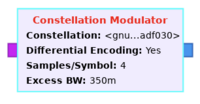
The Constellation Modulator block appears as follows:
The Constellation parameter is the ID of the Constellation Rect. Object (qpsk), even though it shows on the flowgraph as something else.
The Differential Encoding parameter determines whether or not to apply this encoding. Differential encoding allows transmission based on the relative phase transitions between symbols. It makes demodulation easier by avoiding the challenges of absolute phase recovery caused by phase offsets and ambiguities between the transmitter and receiver. For many cases, however, the relative phase change between symbols remains consistent. Therefore, differential encoding simplifies demodulation at the cost of higher bit error rates. For these reasons, we use differential encoding in this tutorial to make demodulation less complex. For differential encoding and decoding to work with the default GNU Radio blocks, the points in the constellation object must be in clockwise or counterclockwise order.
Samples/Symbol determines the samples per symbol. When dealing with the number of samples per symbol, we want to keep this value as small as possible (minimum value of 2). Generally, we can use this value to help us match the desired bit rate with the sample rate of a hardware device. But since we're using simulation, the samples per symbol is only important in making sure we match this rate throughout the flowgraph. We'll use 4 here, which is greater than what we need, but useful to visualize the signal in the different domains.
More details regarding the Excess Bandwidth parameter are given below.
Excess Bandwidth
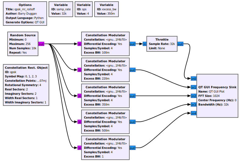
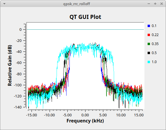
The constellation modulator uses a root raised cosine (RRC) pulse shaping filter to control the bandwidth of the transmit signal. That parameter is called "Excess BW" (excess bandwidth).
The flowgraph below, Media:Qpsk_rrc_rolloff.grc, generates the following figure showing different values of the excess bandwidth. Typical values used are between 0.2 (red trace) and 0.35 (green trace). We will use 0.35 in this tutorial.
Matched Filters and ISI
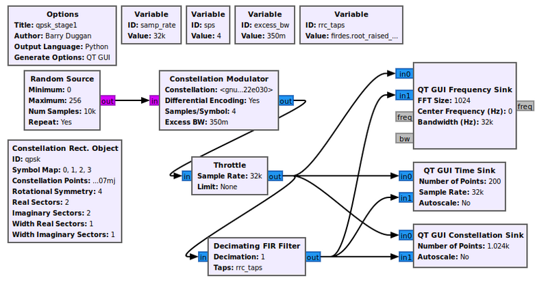
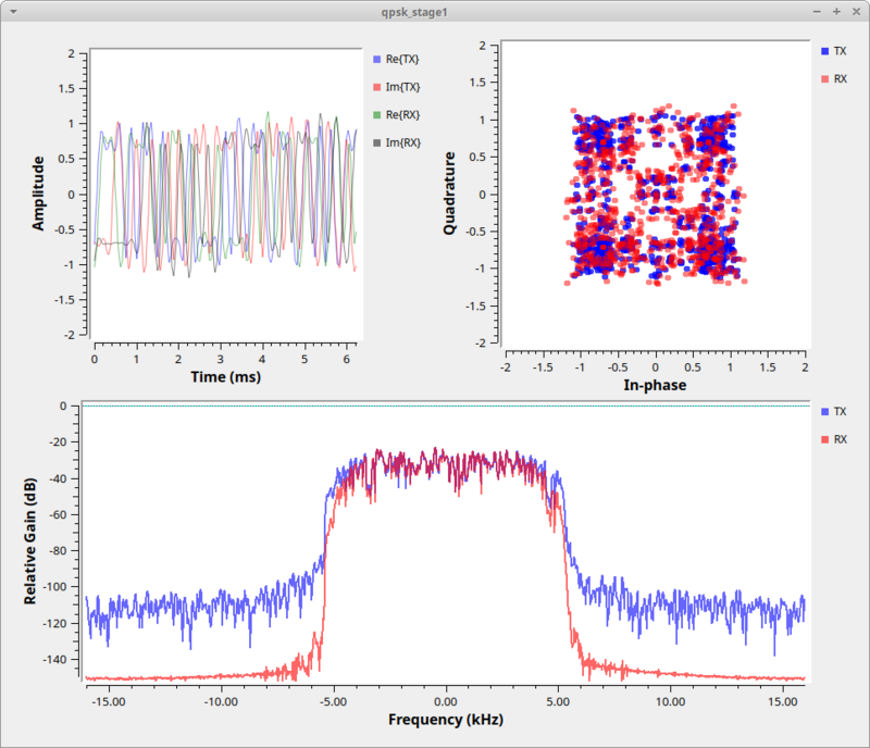
The example flowgraph, Media:Qpsk_stage1.grc, transmits a QPSK constellation. It plots both the transmitted signal and part of the receiver chain in time, frequency, and the constellation plot. The variable rrc_taps value is firdes.root_raised_cosine(1.0,samp_rate,samp_rate/sps,excess_bw,11*sps).
In the constellation plot below, we see the effects of the up-sampling (generating 4 samples per symbol) and filtering process. The RRC filter limits the transmit bandwidth so the signal is within our desired bandwidth. If we didn't put a shaping filter on the signal, we would be transmitting square waves which produce a lot of energy in the adjacent channels.
A side effect of the RRC filter is to create inter-symbol interference (ISI). ISI is bad for a received signal because it blurs the symbols together. We'll look into this in-depth during the timing recovery section.
On the receive side, we get rid of ISI by using another filter. Basically, what we've done is used a filter on the transmitter, the RRC filter, which creates the ISI. But when we convolve two RRC filters together, we get a raised cosine filter (which is a form of a Nyquist filter). So, knowing this property of the transmit RRC filter, we can use another RRC filter at the receiver to minimize ISI.
Channel Impairments
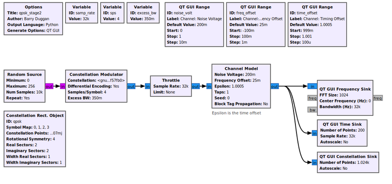
The first stage example only dealt with the mechanics of transmitting a QPSK signal. We'll now look into the effects of the channel and how the signal is distorted between when it was transmitted and when we see the signal in the receiver. The first step is to add a channel model, which is done using the example Media:Qpsk_stage2.grc below. We'll use the basic Channel Model block of GNU Radio.
This block allows us to simulate a few main issues that we have to deal with. The first issue with receivers is noise. Thermal noise in our receiver causes noise that we know of as Additive White Gaussian Noise (AWGN). We set the noise power by adjusting the noise voltage value of the channel model. We specify the voltage here instead of power because we need to know the bandwidth of the signal in order to calculate the power properly. We can calculate the noise voltage from a desired power level knowing the other parameters of the simulation.
Another significant problem between two radios is different clocks, which drive the frequency of the radios. The clocks are, for one thing, imperfect, and therefore different between radios. One radio transmits nominally at fc (say, 450 MHz), but the imperfections mean that it is really transmitting at fc + f_delta_1. Meanwhile, the other radio has a different clock and therefore a different offset, f_delta_2. When it's set to fc, the real frequency is at fc + f_delta_2. In the end, the received signal will be f_delta_1 + f_delta_2 off where we think it should be (these deltas may be positive or negative).
Related to the clock problem is the ideal sampling point. We've up-sampled our signal in the transmitter and shaped it, but when receiving it, we need to sample the signal at the original sampling point in order to maximize the signal power and minimize the inter-symbol interference. Like in our stage 1 simulation after adding the second RRC filter, we can see that among the 4 samples per symbol, one of them is at the ideal sampling point of +1, -1, or 0. But again, the two radios are running at different speeds, so the ideal sampling point is an unknown.
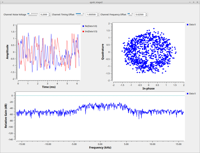
The second stage of our simulation allows us to play with these effects of additive noise, frequency offset, and timing offset. When we run this graph we have added a bit of noise (0.2), some frequency offset 0.025), and some timing offset (1.0005) to see the resulting signal.
The constellation plot shows us a cloud of samples, far worse that what we started off with in the last stage. From this received signal, we now have to undo all of these effects.
Receiving a QPSK signal
Polyphase Clock Sync
The Polyphase Clock Sync provides three functions. First, it performs the clock recovery. Second, it provides the receiver matched filter to remove the ISI. Third, it down-samples the signal (reduces the samples per symbol).
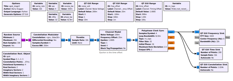
The example flowgraph Media:Qpsk_stage3.grc takes the output of the channel model and passes it through a Polyphase Clock Sync block. This block is setup with 32 filters and a loop bandwidth of 2pi/100. The block also takes in a value for the expected samples per symbol.
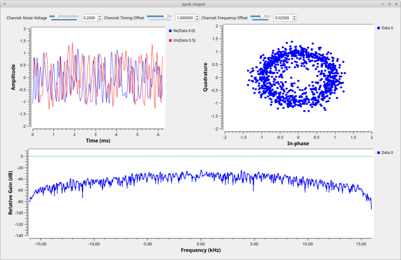
When running this script, we see the constellation is still a little noisy as a result of the ISI after the 32 filters, but is quickly absorbed by noise once we adjust the channel Noise Voltage setting to be more than 0.
Multipath
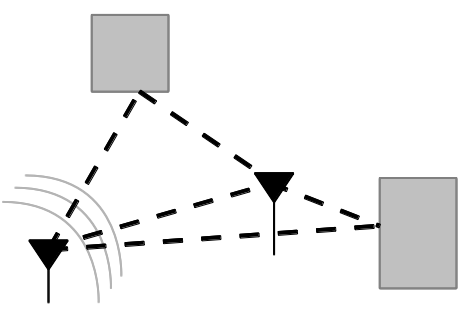
Multipath results from that fact that in most communication environments, we don't have a single path for the signal to travel from the transmitter to the receiver. Like the drawing below shows, any time there is an object that is reflective to the signal, a new path can be established between the two nodes. Surfaces like buildings, signs, trees, people, etc. can all produce signal reflections. Each of these reflective paths will show up at the receiver at different times based on the length of the path. Summing these together at the receiver causes distortions, both constructively and destructively.
Equalizer
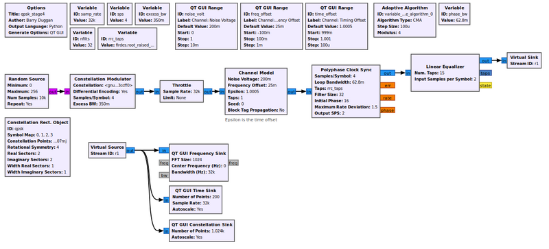
The Adaptive Algorithm has a CMA algorithm type, or Constant Modulus Algorithm. It is a blind equalizer, but it only works on signals that have a constant amplitude, or modulus. This means that digital signals like QPSK are good candidates since they have points only on the unit circle. The Media:Qpsk_stage4.grc flowgraph illustrates this point.
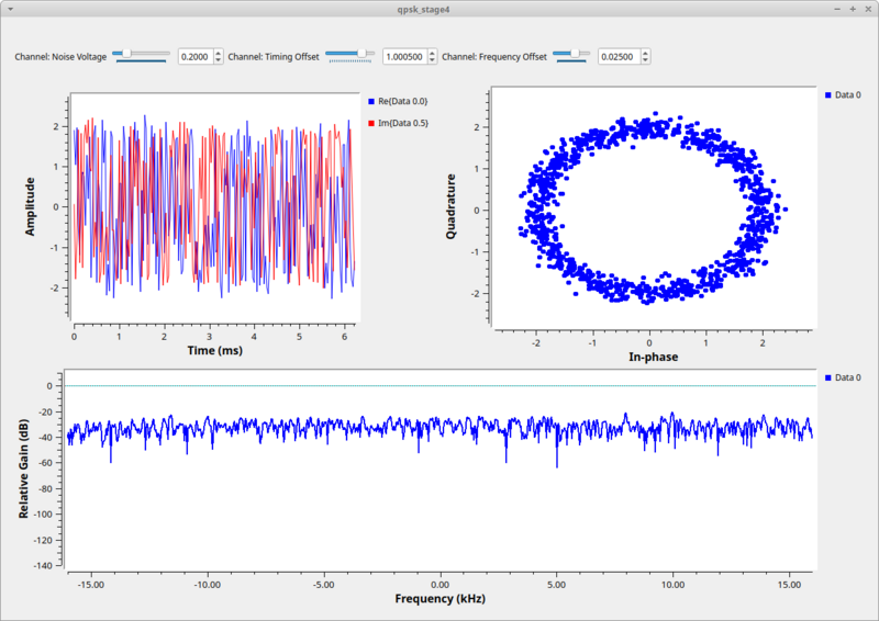
We can watch the CMA algorithm converge. Note, too, that since we have both a clock sync and equalizer block, they are converging independently, but the one stage will affect the next stage. So there is some interaction going on here while both are locking on to the signal. In the end, though, we can see the effect of the time-locked multipath signal before and after the equalizer. Before the equalizer, we have a very ugly signal, even without noise. The equalizer nicely figures out how to invert and cancel out this channel so that we have a nice, clean signal again. We can also see the channel itself and how it flattens out nicely after the equalizer.
Phase and Frequency Correction
Given that we've equalized the channel, we still have a problem of phase and frequency offset. Equalizers tend not to adapt quickly, and so a frequency offset easily can be beyond the ability of the equalizer to keep up. Also, if we're just running the CMA equalizer, all it cares about is converging to the unit circle. It has no knowledge of the constellation, so when it locks, it will lock at any given phase. We now need to correct for any phase offset as well as any frequency offset.
Two things about this stage. First, we'll use a second order loop so that we can track both phase and frequency (which is the derivative of the phase) over time. Second, the type of recovery we'll deal with here assumes that we are doing fine frequency correction. So we must be sure that we are already within a decent range of the ideal frequency. If we are too far away, our loop here won't converge and we'll continue to spin. There are ways to do coarse frequency correction, such as the FLL_Band-Edge block, but we won't get getting into those here.
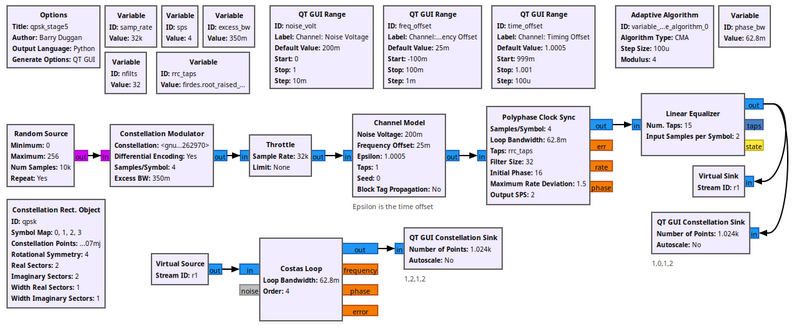
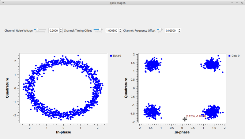
For this task, we're going to use the Costas Loop in example Media:Qpsk_stage5.grc. The Costas Loop block can synchronize BPSK, QPSK, and 8PSK. Like all of our others, it uses a second order loop and is therefore defined with a loop bandwidth parameter. The other thing it needs to know is the order of the PSK modulation, so 2 for BPSK, 4 for QPSK, and 8 for 8PSK.
After the equalizer, the symbols are all on the unit circle, but rotating due to the frequency offset. At the output of the Costas loop block, we can see the locked constellation like we started with (plus the extra noise).
Decoding
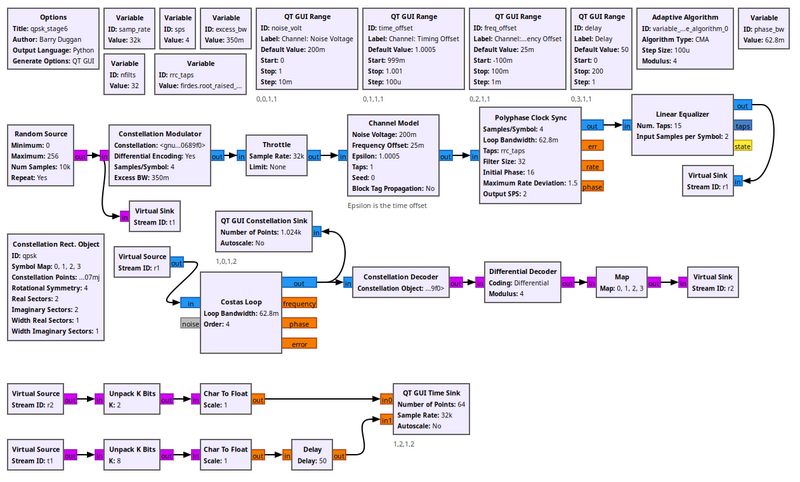
Media:Qpsk_stage6.grc contains our final flowgraph to decode the signal. First, we insert a Constellation Decoder after the Costas loop, but our work is not quite done. At this point, we get our symbols from 0 to 3 because this is the size of our alphabet in a QPSK scheme. But, of those 0-3 symbols, how do we know for sure that we have the same mapping of symbols to constellation points that we did when we transmitted? Notice in our discussion above that nothing we did had any knowledge of the transmitted symbol-to-constellation mapping, which means we might have an ambiguity of 90 degrees in the constellation. Luckily, we avoided this problem by transmitting differential symbols. We didn't actually transmit the constellation itself, we transmitted the difference between symbols of the constellation by setting the Differential setting in the Constellation Modulator block to True.
The flowgraph uses the Differential Decoder to translate the differential coded symbols back to their original symbols due to the phase transitions, not the absolute phase itself. But even out of here, our symbols are not exactly right. This is the hardest part about demodulation. In the synchronization steps, we had basic physics and math on our side. Now, though, we have to interpret some symbol based on what someone else said it was. Basically we just have to know this mapping. And luckily we do, so we use the Map block to convert the symbols from the differential decoder to the original symbols we transmitted. At this point, we now have the original symbols from 0-3, so lets unpack those 2 bits per symbol into bits using the unpack bits block. Now we have the original bit stream of data!
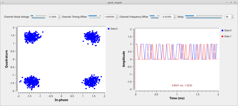
But how do we know that it's the original bit stream? We'll compare the received stream to the input stream, which we can do because this is a simulation and we have access to the transmitted data. But of course, the transmitter produced packed bits, so we again use the unpack bit block to unpack from 8-bits per byte to 1-bit per byte. We then convert these streams to floating point values of 0.0 and 1.0 simply because our time sinks only accept float and complex values. Comparing these two directly would show us... nothing. Why? Because the receiver chain has many blocks and filters that delay the signal, so the received signal is some number of bits behind. To compensate, we have to delay the transmit bits by the same amount using the Delay block. You can then adjust the delay to find the correct value and see how the bits synchronize. Note: wait a few seconds after each change of the delay value. Hint: the correct value is 58.
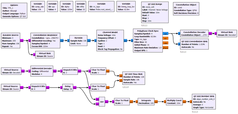
Media:QPSK.grc contains a version that permits calculating the correct delay whose value is : int(5.5 * sps + 7)*2. Thus even for a different sps value, the delay will be automatically adjusted.
Using the Symbol Sync block
The Polyphase_Clock_Sync block will be deprecated in a future GNU Radio version (after v3.10.9.0). The replacement for it is a Symbol_Sync block. There is a good explanation of how the Symbol Sync block works in the block documentation, including a link to a GRCon17 presentation about it.
The stage6 source code using the Symbol Sync block is here. The flowgraph is shown below.

