Sample Rate Change: Difference between revisions
Jump to navigation
Jump to search
Mattcarrick (talk | contribs) No edit summary |
Mattcarrick (talk | contribs) |
||
| Line 10: | Line 10: | ||
Start by adding the following blocks to the flowgraph and connect them: | Start by adding the following blocks to the flowgraph and connect them: | ||
# ''Variable'' | # Two ''Variable'' blocks | ||
# ''Low-Pass Filter Taps'' | # ''Low-Pass Filter Taps'' | ||
# ''QT GUI Range'' | # ''QT GUI Range'' | ||
| Line 19: | Line 19: | ||
[[File:InterpolationFlowgraphStart.png|700px]] | [[File:InterpolationFlowgraphStart.png|700px]] | ||
== Decimation == | == Decimation == | ||
Revision as of 21:45, 12 January 2022
This tutorial describes how to implement sample rate change within GNU Radio.
The previous tutorial, Designing Filter Taps, demonstrates how to design filter taps and use them in signal processing blocks. Please complete the Designing Filter Taps tutorial before completing this one.
Interpolation
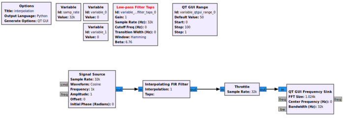
Interpolation is the process of increasing the sampling rate and thus the available bandwidth. This example will demonstrate how to increase the sampling rate using the Interpolating FIR Filter block.
Start by adding the following blocks to the flowgraph and connect them:
- Two Variable blocks
- Low-Pass Filter Taps
- QT GUI Range
- Signal Source
- Interpolating FIR Filter
- Throttle
- QT Frequency GUI Sink
Decimation
Rational Rate Resampling
Arbitrary Rate Resampling
- updating sample rate variable
