Simulation example: BPSK Demodulation: Difference between revisions
(initial creation) |
m (add comments) |
||
| Line 1: | Line 1: | ||
This tutorial is a follow-on to the [[Guided_Tutorial_PSK_Demodulation|'''Example Usage of GNU Radio: PSK Modulation / Demodulation''']] tutorial to present the use of BPSK rather than QPSK. <b>It is imperative that all | This tutorial is a follow-on to the [[Guided_Tutorial_PSK_Demodulation|'''Example Usage of GNU Radio: PSK Modulation / Demodulation''']] tutorial to present the use of BPSK rather than QPSK. <b>It is imperative that all of the prerequisites are studied before doing this one.</b> Only sections which differ from the QPSK tutorial are discussed in detail. | ||
The difference between QPSK and BPSK is the number of bits per symbol. QPSK uses 2 bit symbols; BPSK uses 1 bit symbols. In both cases, the Constellation Modulator block uses all 8 input bits. Note that the Constellation Object is different between QPSK and BPSK. | |||
== Prerequisites == | == Prerequisites == | ||
| Line 33: | Line 35: | ||
Recovering timing is the same as described in the QPSK tutorial section [[Guided_Tutorial_PSK_Demodulation#Recovering_Timing|Recovering Timing]]. | Recovering timing is the same as described in the QPSK tutorial section [[Guided_Tutorial_PSK_Demodulation#Recovering_Timing|Recovering Timing]]. | ||
== Equalizers == | |||
The CMA Equalizer has been left out of this tutorial to simplify the final flowgraph. | |||
== Phase and Fine Frequency Correction == | == Phase and Fine Frequency Correction == | ||
Revision as of 14:13, 28 August 2020
This tutorial is a follow-on to the Example Usage of GNU Radio: PSK Modulation / Demodulation tutorial to present the use of BPSK rather than QPSK. It is imperative that all of the prerequisites are studied before doing this one. Only sections which differ from the QPSK tutorial are discussed in detail.
The difference between QPSK and BPSK is the number of bits per symbol. QPSK uses 2 bit symbols; BPSK uses 1 bit symbols. In both cases, the Constellation Modulator block uses all 8 input bits. Note that the Constellation Object is different between QPSK and BPSK.
Prerequisites
- Tutorials:
Transmitting a Signal
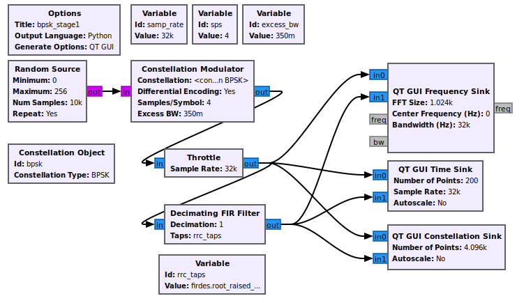
The first stage is transmitting the BPSK signal. We generate a stream of bits and modulate it onto a complex constellation. To do this, we use the Constellation Modulator block, which uses a Constellation Object and other settings to control the transmitted signal.
The constellation object allows us to determine how the symbols are coded. The modulator block can then use this modulation scheme with or without differential encoding. The constellation modulator expects packed bytes, so we have a random source generator providing bytes with values 0 - 255.
When dealing with the number of samples per symbol, we want to keep this value as small as possible (minimum value of 2). Generally, we can use this value to help us match the desired bit rate with the sample rate of the hardware device we'll be using. Since we're using simulation, the samples per symbol is only important in making sure we match this rate throughout the flowgraph. We'll use 4 here, which is greater than what we need, but useful to visualize the signal in the different domains.
Finally, we set the excess bandwidth value. The constellation modulator uses a root raised cosine (RRC) pulse shaping filter, which gives us a single parameter to adjust the roll-off factor of the filter, often known mathematically as 'alpha'.
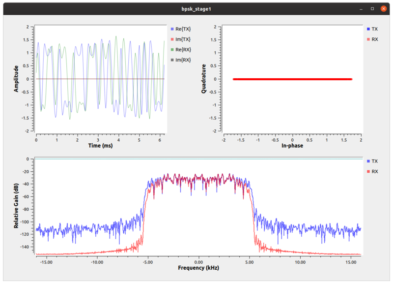
In the constellation plot, we see the effects of the up-sampling (generating 4 samples per symbol) and filtering process. Note that all of the points lie along the In-phase axis. The RRC filter adds intentional self-interference, known as inter-symbol interference (ISI). ISI is bad for a received signal because it blurs the symbols together. We'll look into this in-depth during the timing recovery section. Right now, let's just see what we're doing to the signal. If you are just looking at the transmitted signals from this graph, then you should see that the frequency plot is showing a signal with a nice shape to it and that rolls-off into the noise. If we didn't put a shaping filter on the signal, we would be transmitting square waves that produce a lot of energy in the adjacent channels. By reducing the out-of-band emissions, our signal now stays nicely within our channel's bandwidth.
On the receive side, we get rid of the ISI by using another RRC filter. Basically, what we've done is used a filter on the transmitter, the RRC filter, that creates the ISI but controls the bandwidth and then another RRC filter at the receiver. When we convolve the two RRC filters, we get a raised cosine filter. The output of the receive-side RRC filter is a raised cosine shaped signal with minimized ISI.
Adding Channel Impairments
Adding channel impairments is the same as described in the QPSK tutorial section Adding Channel Impairments.
Recovering Timing
Recovering timing is the same as described in the QPSK tutorial section Recovering Timing.
Equalizers
The CMA Equalizer has been left out of this tutorial to simplify the final flowgraph.
Phase and Fine Frequency Correction
Phase and Fine Frequency Correction is the same as described in the QPSK tutorial section Phase and Fine Frequency Correction.
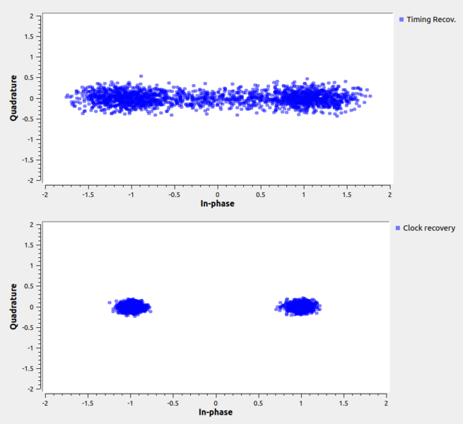
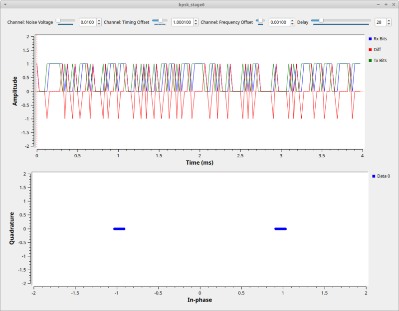
Here is the BPSK output screen:
Decoding
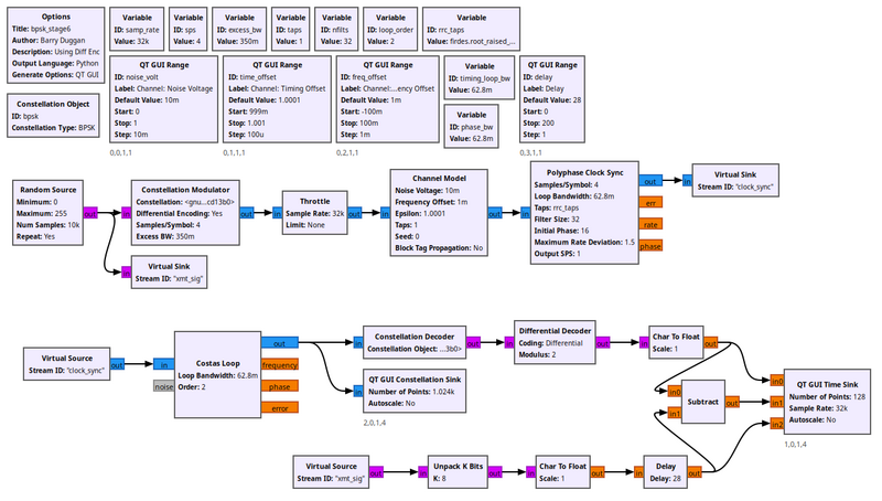
Now that the hard part is done, we get to decode the signal. Using the example flowgraph below, we insert a Constellation Decoder after the Costas loop, but our work is not quite done. At this point, we get our symbols 0 and 1 because this is the size of our alphabet in a BPSK scheme. But how do we know for sure that we have the same mapping of symbols to constellation points that we did when we transmitted? Notice in our discussion above that nothing we did had any knowledge of the transmitted symbol-to-constellation mapping, which means we might have an ambiguity of 180 degrees in the constellation. Luckily, we avoided this problem by transmitting differential symbols. We didn't actually transmit the constellation itself, we transmitted the difference between symbols of the constellation by setting the Differential setting in the Constellation Modulator block to 'Yes'. So now we undo that.
The flowgraph uses the Differential Decoder block to translate the differential coded symbols back to their original symbols based on the phase transitions, not the absolute phase itself. Now we have the original bit stream!
But how do we know that it's the original bit stream? To verify that, we'll compare it to the input bit stream, which we can do because this is a simulation and we have access to the transmitted data. But of course, the transmitter produced packed bits, so we use the unpack bit block to unpack from 8-bits per byte to 1-bit per byte. We then convert these streams to floating point values of 0.0 and 1.0 simply because our time sinks only accept float and complex values. Comparing these two directly would show us... nothing. Why? Because the receiver chain has many blocks and filters that delay the signal, so the received signal is some number of bits behind. To compensate, we have to delay the transmitted bits by the same amount using the Delay block. Then you can adjust the delay to find the correct value and see how the bits synchronize. Also you can subtract one signal from the other to see when they are synchronized because the output will be 0. Adding noise and other channel affects then can be seen easily as bit errors whenever this signal is not 0.
