Low Pass Filter Example
This tutorial describes how to use a low-pass filter in GNU Radio.
The previous tutorial, Hier Blocks and Parameters, demonstrates how to create a Hierarchical Block in GRC and use Parameters. The next tutorial, Designing_Filter_Taps, describes how to design a set of low-pass filter taps and apply them against a signal.
Creating the Flowgraph
Begin by adding the following blocks to the GRC work space:
- Signal Source
- Low Pass Filter
- Throttle
- QT GUI Frequency Sink
- QT GUI Range
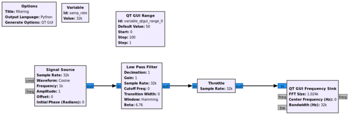
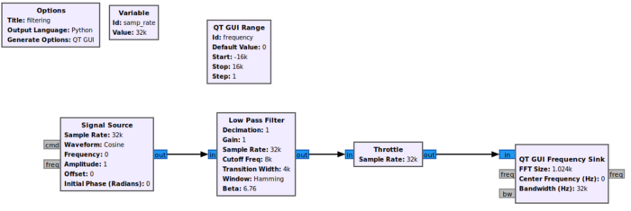
Connect the blocks in the following manner:
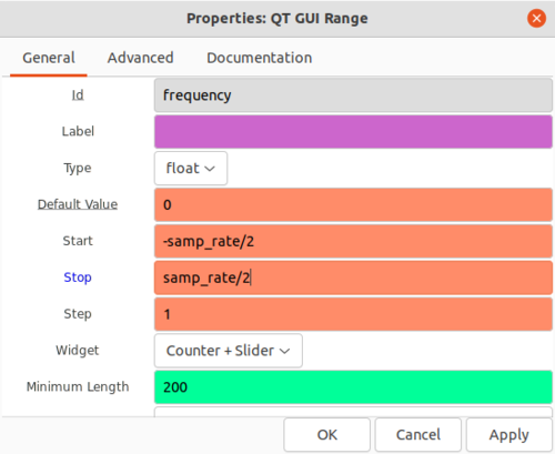
The QT GUI Range block will be used to control the frequency of the Signal Source block. Double-click the QT GUI Range block and edit the properties:
- Id: frequency
- Default Value: 0
- Start: -samp_rate/2
- Stop: samp_rate/2
Click OK to save.
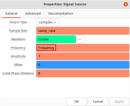
Double-click the Signal Source block and enter frequency from the QT GUI Range variable:
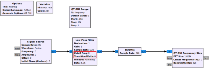
Click OK to save. The flowgraph will look like the following image. Notice that the Low Pass Filter has a Cutoff Freq and Transition Width of 0:
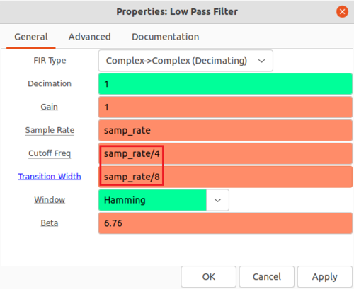
Double-click the Low Pass Filter block and edit the properties:
- Cutoff freq: samp_rate/4
- Transition Width: samp_rate/8
The flowgraph is now complete and should look like the following:
Run the Flowgraph
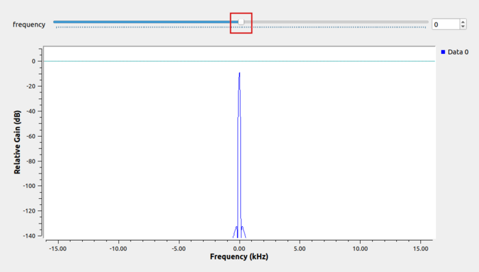
The flowgraph is now complete! Run the flowgraph. The QT GUI Frequency Sink will appear with a frequency slider bar:
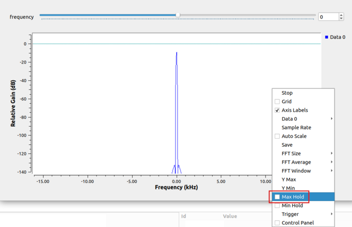
Mouse-click on the QT GUI Frequency window and select Max Hold:
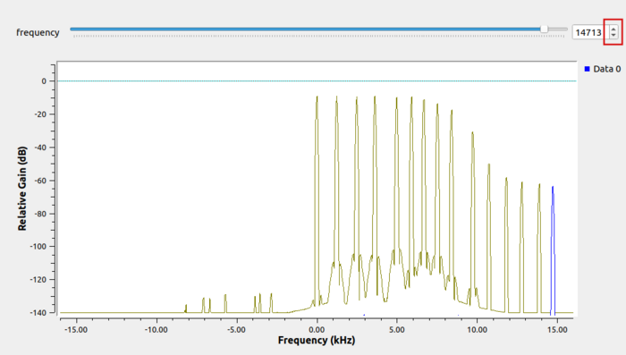
The Max Hold option will retain and display the maximum value at each frequency until the the flowgraph is closed. Clicking through multiple values of the frequency slider bar at the top will show the low pass filter response:
The next tutorial, Designing_Filter_Taps, describes how to design a set of low-pass filter taps and apply them against a signal.
