Polyphase Channelizer
(Note: the Hierarchical Polyphase Channelizer block may be easier to use.)
Overview
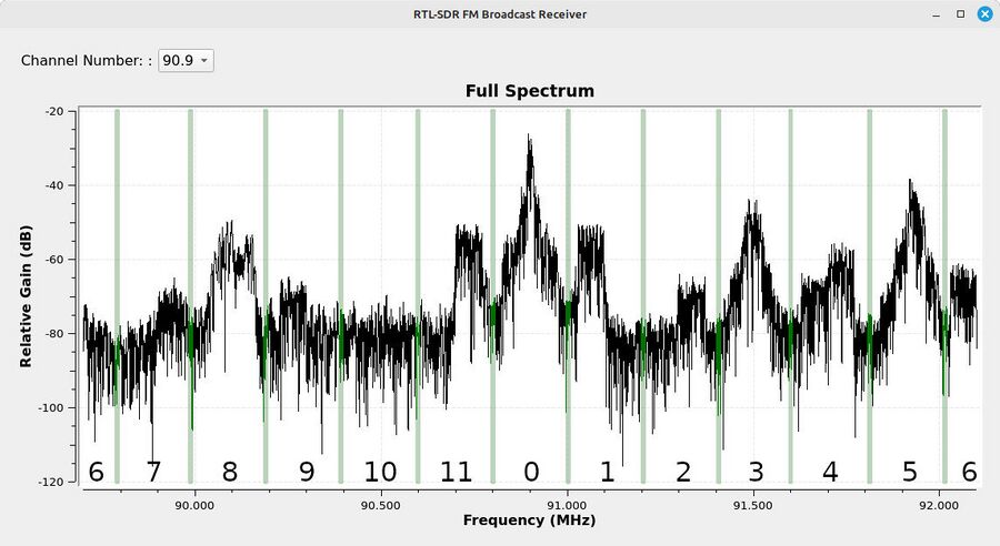
This block takes a stream of samples and partitions it into a set of equal-bandwidth channels. Each of the resulting channels is decimated to a new sample rate that is the input sampling rate divided by the number of channels. For example, using this block on a 2.4 MHz-wide portion of the FM broadcast band, then partitioned into 12 channels would be similar to that shown below.
This is how a portion of the FM broadcast spectrum can be channelized into 12 channels based on a sample stream with a 2.4 MHz sample rate. The numbers at the bottom of the display are the channel numbers as created by the block, and can be mapped to different outputs based on the Channel Map in the block parameters.
Parameters
- Channels
- Specifies the number of channels
- Taps
- The prototype filter to populate the filterbank. The taps can be generated using the firdes command.
- Oversampling Ratio
- The over sampling rate is the ratio of the the actual output sampling rate to the normal output sampling rate. It must be rationally related to the number of channels as N/i for i in [1,N], which gives an outputsample rate of [fs/N, fs] where fs is the input sample rate and N is the number of channels. For example, for 6 channels with fs = 6000 Hz, the normal rate is 6000/6 = 1000 Hz. Allowable oversampling rates are 6/6, 6/5, 6/4, 6/3, 6/2, and 6/1 where the output sample rate of a 6/1 oversample ratio is 6000 Hz, or 6 times the normal 1000 Hz. A rate of 6/5 = 1.2, so the output rate would be 1200 Hz.
- Attenuation
- Attenuation of stop band.
- Sample Delay
- Sample delay of filter.
- Channel Map
- The Channel Map can be used to rearrange which channels go to which output stream. See Channel Map.
- Bus Connections
- No idea. Default is [[0,],]
How To Set the Parameters
The process for setting up this block are as follows:
- Determine the sample rate based on the channel spacing and number of channels. The sample rate should be (channel spacing)*(number of channels). Ex: Aircraft communications are typically spaced 25 kHz apart. If we want a system that captures 40 channels, we would need (25 kHz)(40 channels) = 1 MHz sample rate.
- Determine parameters for the lowpass filter. Ex: Aircraft communications with a 25 kHz spacing typically require up to 10 kHz for the actual communications (DSB-FC-AM). Thus, a lowpass filter to pass such communications could use a passband of 5 kHz (1/2 of the 10 kHz) and the remaining 7.5 kHz for the transition width.
- Use the appropriate code to generate the filter taps. Ex: Using the example above, we can use a Blackman-harris window for such a filter. A basic lowpass filter can be created using the firdes filter command. Such a filter would be: firdes.low_pass(1,samp_rate,5e3,7.5e3,5).
- Determine if oversampling is required. If not needed, leave the default of 1. Otherwise, the filter output can also be oversampled. The over sampling rate is the ratio of the the actual output sampling rate to the normal output sampling rate. It must be rationally related to the number of channels as N/i for i in [1,N], which gives an outputsample rate of [fs/N, fs] where fs is the input sample rate and N is the number of channels.
- Generate the channel map. Channel 0 is always in the middle of the spectrum. For a flowgraph with an odd number of channels, there will be an equal number of channels higher and lower in the spectrum. For an even number of channels, the channel that is 1/2 of the total number will be split betweeen the lowest and highest frequency of the spectrum. (NOTE: This latter concept is shown in the image above, where channel 6 is split half being at the top end of the spectrum, and the other half at the bottom end of the spectrum.) A channel map that follows this numbering scheme will have the spectrum output in order of frequency. For example, for a 5 channel scheme, the channel map of [3,4,0,1,2] will have the lowest frequency channel on output 0, and the highest frequency on output 4.
Example
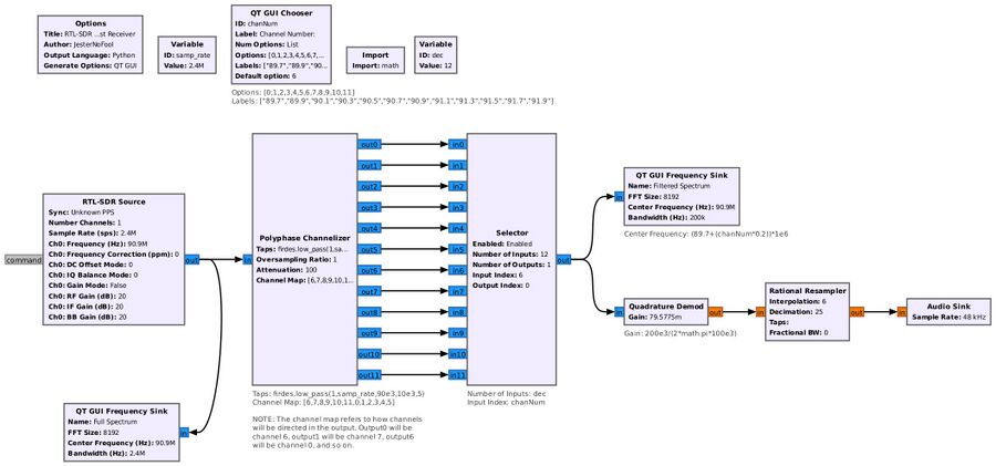
This is an example to channelize 12 channels of the FM broadcast band using a RTL-SDR. The RTL-SDR center frequency is set such that it is centered on a FM channel. It provides for simultaneous access to up to 5 channels higher and lower in the spectrum.
When run, this flowgraph provides simultaneous access to 11 channels (the 12th channel, channel 6, is split between the upper and lower ends of the spectrum, and probably is unusable in many, if not most, situations.) The Selector block allows the user to select which channel to process.
References
- Guide on polyphase filterbank blocks.
- Multirate Signal Processing for Communication Systems (Second Edition), fredric j harris, River Publishers, 2021

