QPSK Mod and Demod
NOTICE! This is a work in progress, but ultimately will replace Guided Tutorial PSK Demodulation.
Introduction
Objectives
- Understand issues of signal distortion and channel effects.
- Recognize the stages required to transmit and receive QPSK signals.
Prerequisites
The student should study each of the sections under the "Flowgraph Fundamentals" heading in Tutorials before attempting to do this tutorial.
References
- Our Suggested Reading list
- The ARRL Handbook "Quadrature Modulation" section (any recent edition)
- J. Feigin, "Practical Costas loop design: Designing a simple and inexpensive BPSK Costas loop carrier recovery circuit," RF signal processing, pp. 20-36, 2002
Notes
This tutorial has been revised and tested with GNU Radio version 3.10.8.0. It strives to provide consistent flowgraphs where each stage builds on the previous one, maintaining the same parameters from one stage to the next.
It is intended that the reader study the flowgraphs and resulting output, but not necessarily build each one. However, links to GRC source files are included.
Transmitting a QPSK Signal
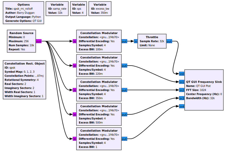
The first stage is transmitting the QPSK signal. We generate a stream of bits and modulate it onto a complex constellation. To do this, we use the Constellation Modulator block, which uses a Constellation Rect. Object and other settings to control the transmitted signal. The Constellation parameter of the Constellation Modulator is the id of the Constellation Rect. Object (qpsk), even though it shows on the flowgraph as something else.
The constellation object specifies how the symbols are coded. The modulator block can then use this modulation scheme with or without differential encoding. The constellation modulator expects packed bytes, so we have a random source generator providing bytes with values of 0 to 255.
When dealing with the number of samples per symbol, we want to keep this value as small as possible (minimum value of 2). Generally, we can use this value to help us match the desired bit rate with the sample rate of a hardware device. But since we're using simulation, the samples per symbol is only important in making sure we match this rate throughout the flowgraph. We'll use 4 here, which is greater than what we need, but useful to visualize the signal in the different domains.
Excess Bandwidth
The constellation modulator uses a root raised cosine (RRC) pulse shaping filter to control the bandwidth of the transmit signal. That parameter is called "Excess BW" (excess bandwidth).
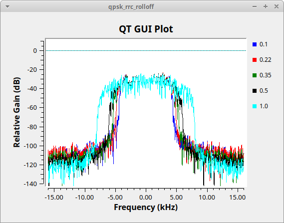
The flowgraph below, Media:Qpsk_rrc_rolloff.grc, generates the following figure showing different values of the excess bandwidth. Typical values used are between 0.2 (red trace) and 0.35 (green trace). We will use 0.35 in this tutorial.

