VCO: Difference between revisions
Jump to navigation
Jump to search
m (add brackets to link) |
(moved complex source files to VCO (complex)) |
||
| (7 intermediate revisions by 2 users not shown) | |||
| Line 11: | Line 11: | ||
; Sensitivity | ; Sensitivity | ||
: units are radians/sec/ | : units are radians/sec/(input unit) | ||
; Amplitude | ; Amplitude | ||
| Line 17: | Line 17: | ||
== Example Flowgraph == | == Example Flowgraph == | ||
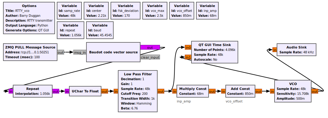
This flowgraph can be found at [https://github.com/duggabe/gr-RTTY-basics/tree/master/RTTY_xmt] | |||
[[File:RTTY_vco_fg.png]] | [[File:RTTY_vco_fg.png]] | ||
| Line 22: | Line 24: | ||
For this flowgraph, the standard RTTY tones of 2295 (mark) and 2125 (space) are generated. The calculations for this follow: | For this flowgraph, the standard RTTY tones of 2295 (mark) and 2125 (space) are generated. The calculations for this follow: | ||
* Choosing a full-scale frequency of 2500Hz with an input of +1, the VCO Sensitivity = (2 * | * Choosing a full-scale frequency of 2500Hz with an input of +1.0, the VCO Sensitivity = (2 * math.pi * 2500 / 1.0) = 15708 | ||
* | * At the output of the Low Pass Filter, a Mark has a value of +1.0 and a Space has a value of 0.0 | ||
* | * When the output of the Low Pass Filter is +1.0, the input of the VCO is (1.0 * 0.068) + 0.850 = 0.918 That generates a frequency of 0.918 * 2500 => 2295 | ||
* When the output of the Low Pass Filter is 0.0, the input of the VCO is (0.0 * 0.068) + 0.850 = 0.850 That generates a frequency of 0.850 * 2500 => 2125 | |||
See [[Sample_Rate_Tutorial#Sink_hardware_example]] for a discussion of the timing involved in a similar flowgraph. | See [[Sample_Rate_Tutorial#Sink_hardware_example]] for a discussion of the timing involved in a similar flowgraph. | ||
| Line 31: | Line 34: | ||
; C++ files | ; C++ files | ||
: [https://github.com/gnuradio/gnuradio | : [https://github.com/gnuradio/gnuradio/blob/main/gr-blocks/lib/vco_f_impl.cc vco_f_impl.cc] | ||
; Header files | ; Header files | ||
: [https://github.com/gnuradio/gnuradio | : [https://github.com/gnuradio/gnuradio/blob/main/gr-blocks/lib/vco_f_impl.h vco_f_impl.h] | ||
; Public header files | ; Public header files | ||
: [https://github.com/gnuradio/gnuradio | : [https://github.com/gnuradio/gnuradio/blob/main/gr-blocks/include/gnuradio/blocks/vco_f.h vco_f.h] | ||
; Block definition | ; Block definition | ||
: [https://github.com/gnuradio/gnuradio | : [https://github.com/gnuradio/gnuradio/blob/main/gr-blocks/grc/blocks_vco_f.block.yml blocks_vco_f.block.yml] | ||
Latest revision as of 13:31, 13 April 2024
VCO - Voltage controlled oscillator. Produces a sinusoid of frequency based on the amplitude of the input. See VCO (complex) for a complex sinusoidal output.
input: float stream of control voltages;
output: float oscillator output
Parameters
- Sample Rate
- sampling rate (Hz)
- Sensitivity
- units are radians/sec/(input unit)
- Amplitude
- output amplitude
Example Flowgraph
This flowgraph can be found at [1]
For this flowgraph, the standard RTTY tones of 2295 (mark) and 2125 (space) are generated. The calculations for this follow:
- Choosing a full-scale frequency of 2500Hz with an input of +1.0, the VCO Sensitivity = (2 * math.pi * 2500 / 1.0) = 15708
- At the output of the Low Pass Filter, a Mark has a value of +1.0 and a Space has a value of 0.0
- When the output of the Low Pass Filter is +1.0, the input of the VCO is (1.0 * 0.068) + 0.850 = 0.918 That generates a frequency of 0.918 * 2500 => 2295
- When the output of the Low Pass Filter is 0.0, the input of the VCO is (0.0 * 0.068) + 0.850 = 0.850 That generates a frequency of 0.850 * 2500 => 2125
See Sample_Rate_Tutorial#Sink_hardware_example for a discussion of the timing involved in a similar flowgraph.
Source Files
- C++ files
- vco_f_impl.cc
- Header files
- vco_f_impl.h
- Public header files
- vco_f.h
- Block definition
- blocks_vco_f.block.yml
