VCO (complex): Difference between revisions
Jump to navigation
Jump to search
(there's no volts in digital signal processing) |
|||
| Line 26: | Line 26: | ||
; C++ files | ; C++ files | ||
: [https://github.com/gnuradio/gnuradio | : [https://github.com/gnuradio/gnuradio/blob/main/gr-blocks/lib/vco_c_impl.cc vco_c_impl.cc] | ||
; Header files | ; Header files | ||
: [https://github.com/gnuradio/gnuradio | : [https://github.com/gnuradio/gnuradio/blob/main/gr-blocks/lib/vco_c_impl.h vco_c_impl.h] | ||
; Public header files | ; Public header files | ||
: [https://github.com/gnuradio/gnuradio | : [https://github.com/gnuradio/gnuradio/blob/main/gr-blocks/include/gnuradio/blocks/vco_c.h vco_c.h] | ||
; Block definition | ; Block definition | ||
: [https://github.com/gnuradio/gnuradio | : [https://github.com/gnuradio/gnuradio/blob/main/gr-blocks/grc/blocks_vco_c.block.yml blocks_vco_c.block.yml] | ||
Latest revision as of 13:29, 13 April 2024
VCO - Voltage controlled oscillator. Produces a sinusoid of frequency based on the amplitude of the input. See VCO for a real (not complex) sinusoidal output.
input: float stream of control voltages;
output: complex oscillator output
Parameters
- Sample Rate
- sampling rate (Hz)
- Sensitivity
- units are radians/sec/(input unit)
- Amplitude
- output amplitude
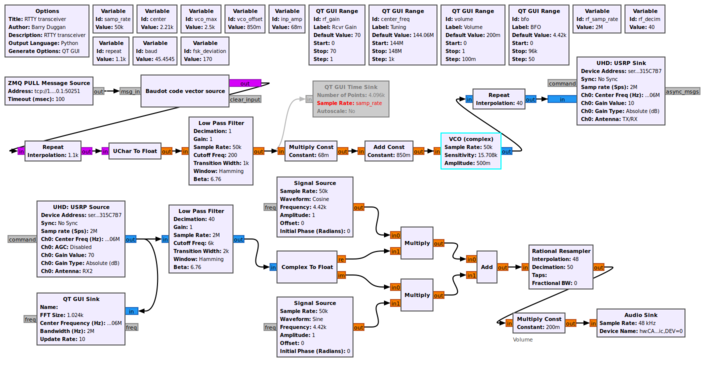
Example Flowgraph
This flowgraph shows a Radioteletype (RTTY) transmitter and receiver. The upper portion is the transmitter. The parameters for the VCO are explained in VCO.
The lower portion of the flowgraph is a single sideband (SSB) receiver. The audio can be fed into a RTTY decoder such as shown in Sample_Rate_Tutorial#Source_hardware_example.
Source Files
- C++ files
- vco_c_impl.cc
- Header files
- vco_c_impl.h
- Public header files
- vco_c.h
- Block definition
- blocks_vco_c.block.yml
