Simulation example: Single Sideband transceiver: Difference between revisions
No edit summary |
|||
| (3 intermediate revisions by 2 users not shown) | |||
| Line 1: | Line 1: | ||
<!-- Simulation_example:_Single_Sideband_transceiver.mediawiki --> | <!-- Simulation_example:_Single_Sideband_transceiver.mediawiki --> | ||
This tutorial explains how a Single Sideband (SSB) signal can be generated and received. Rather than using any real hardware for transmission, the signal is sent via a socket from the transmit section to the receive section. The only actual hardware involved is the computer's microphone input and speaker output. In the case of a Raspberry Pi computer, which has no microphone input, | This tutorial explains how a Single Sideband (SSB) signal can be generated and received. Rather than using any real hardware for transmission, the signal is sent via a socket from the transmit section to the receive section. The only actual hardware involved is the computer's microphone input and speaker output. In the case of a Raspberry Pi computer, which has no microphone input, three alternatives are presented. | ||
This tutorial can be performed with either GNU Radio (GR) version 3.7 or 3.8 (and later). The Graphical User Interface gnuradio-companion (GRC) is used to create a flowgraph for each section. | This tutorial can be performed with either GNU Radio (GR) version 3.7 or 3.8 (and later). The Graphical User Interface gnuradio-companion (GRC) is used to create a flowgraph for each section. | ||
| Line 8: | Line 8: | ||
* [[Guided_Tutorial_GRC|'''Intro to GR usage: GRC and flowgraphs''']] | * [[Guided_Tutorial_GRC|'''Intro to GR usage: GRC and flowgraphs''']] | ||
* [[Sample_Rate_Tutorial|'''Understanding sample rate''']] | * [[Sample_Rate_Tutorial|'''Understanding sample rate''']] | ||
* [[FAQ#The_Community:_Where_you_get_help.2C_advice_and_code|'''Where to get help''']] | |||
== SSB receiver == | == SSB receiver == | ||
| Line 15: | Line 16: | ||
Traditionally, SSB has been created and received using narrow bandpass filters, or by using a "phasing method" requiring a 90 degree phase shift network across the audio spectrum. In 1956 Donald Weaver published a third method in the Proceedings of the IRE ("A Third Method of Generating and Detecting Single Side Band Signals", Dec. 1956). It involves the use of a local oscillator with a frequency in the middle of the audio spectrum (1500Hz) for the I and Q signals separately, and then adding or subtracting them to recover the upper or lower sideband audio. | Traditionally, SSB has been created and received using narrow bandpass filters, or by using a "phasing method" requiring a 90 degree phase shift network across the audio spectrum. In 1956 Donald Weaver published a third method in the Proceedings of the IRE ("A Third Method of Generating and Detecting Single Side Band Signals", Dec. 1956). It involves the use of a local oscillator with a frequency in the middle of the audio spectrum (1500Hz) for the I and Q signals separately, and then adding or subtracting them to recover the upper or lower sideband audio. | ||
=== Flowgraph === | === Receive from a test file === | ||
This section is derived from a tutorial by Dr. Sharlene Katz, California State University, Northridge. See http://www.csun.edu/~skatz/katzpage/sdr_project/sdr/grc_tutorial4.pdf | |||
Download https://www.csun.edu/~skatz/katzpage/sdr_project/sdr/ssb_lsb_256k_complex2.dat.zip and unzip it. | |||
==== Flowgraph ==== | |||
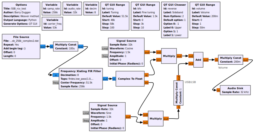
Using gnuradio-companion (GRC) and the following Block descriptions, build this flowgraph of the receiver section:<br> | Using gnuradio-companion (GRC) and the following Block descriptions, build this flowgraph of the receiver test section:<br> | ||
[[File: | [[File:SSB_test_fg.png|861px]] | ||
=== Block descriptions === | ==== Block descriptions ==== | ||
* The Options block identifies the filename for the flowgraph, a title, author, etc. | * The Options block identifies the filename for the flowgraph, a title, author, etc. | ||
** id: | ** id: SSB_rcv_test | ||
** Click on File -> Save As Use the file name ' | ** Click on File -> Save As Use the file name 'SSB_rcv_test'. the extension '.grc' is added automatically | ||
* A Variable block defines the sample rate. | * A Variable block defines the sample rate. | ||
** id: samp_rate | ** id: samp_rate | ||
** value: | ** value: 256000 | ||
* Another Variable block defines the decimation factor. Since the Audio Sink (speaker) uses a sample rate of | * Another Variable block defines the decimation factor. Since the Audio Sink (speaker) uses a sample rate of 32kHz, we will reduce (decimate) the incoming sample rate by a factor of 8. | ||
** id: decim | ** id: decim | ||
** value: | ** value: (int)(samp_rate/audio_rate) | ||
* A QT GUI Chooser allows selection of the Upper or Lower sideband | * A QT GUI Chooser allows selection of the Upper or Lower sideband | ||
* The value of the Sideband selector is used as a multiplier in the Multiply Const block. | * The value of the Sideband selector is used as a multiplier in the Multiply Const block. | ||
** Constant: reverse | ** Constant: reverse | ||
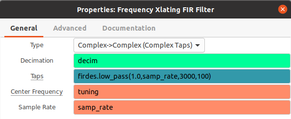
* The Frequency Xlating FIR Filter performs three functions: frequency translation, filtering, and decimation. See [[Frequency_Xlating_FIR_Filter]] for more detail. | |||
[[File:SSB_test_FIR_parms.png]] | |||
* A QT GUI Range block defines an Audio gain (volume) control | * A QT GUI Range block defines an Audio gain (volume) control | ||
** id: volume | ** id: volume | ||
| Line 65: | Line 54: | ||
** Constant: volume | ** Constant: volume | ||
* The speaker output is defined by an Audio Sink block. The parameters are: | * The speaker output is defined by an Audio Sink block. The parameters are: | ||
** Sample rate: set to | ** Sample rate: set to 32kHz (use the pull-down) | ||
** Device name: for most speakers (or headphone jacks) built into the computer, the Device name can be left blank; for other cases, see [[Audio_Sink#Device_Name]] | ** Device name: for most speakers (or headphone jacks) built into the computer, the Device name can be left blank; for other cases, see [[Audio_Sink#Device_Name]] | ||
** OK to block: Yes | ** OK to block: Yes | ||
=== Test receiver section === | ==== Test receiver ==== | ||
To test the receiver, generate and run the flowgraph. After a few seconds, a GUI window will open with the Tuning, Fine tuning, and Volume controls, along with the sideband select push buttons. You should hear KD7LMO on Lower sideband. | |||
To terminate the process cleanly, click on the 'X' in the upper corner of the GUI rather than using Control-C. | |||
=== Simulation receiver === | |||
==== Flowgraph ==== | |||
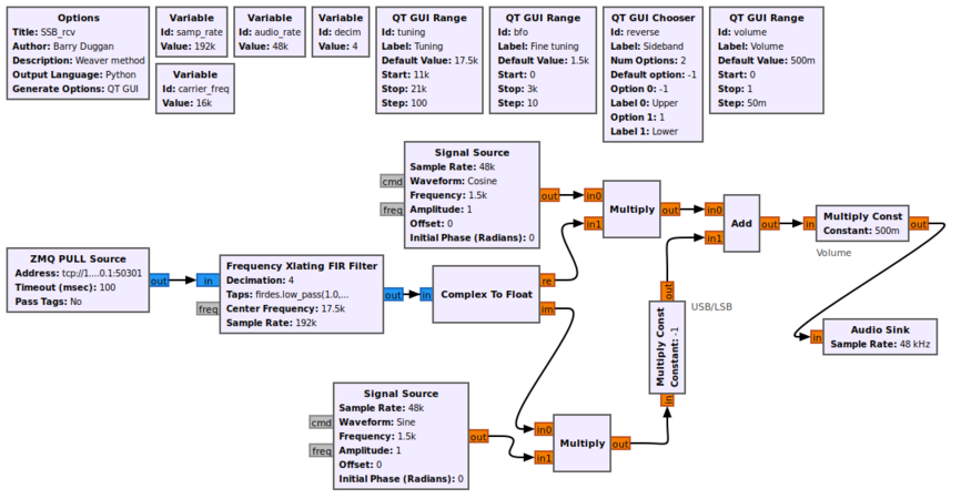
Using gnuradio-companion (GRC) and the following Block descriptions, build this flowgraph (a separate one from the test) for the receiver section:<br> | |||
[[File:SSB_rcv_fg.png|866px]] | |||
==== Block descriptions ==== | |||
<b>Note: Several of the parameters are different from the test flowgraph in the previous section.</b> | |||
* The Options block identifies the filename for the flowgraph, a title, author, etc. | |||
** id: SSB_rcv | |||
** Click on File -> Save As Use the file name 'SSB_rcv'. the extension '.grc' is added automatically | |||
* The signal from the transmitter section is received by the ZMQ PULL Source. It is a 16kHz carrier with a sample rate of 192kHz. | |||
** Address: tcp://127.0.0.1:50301 | |||
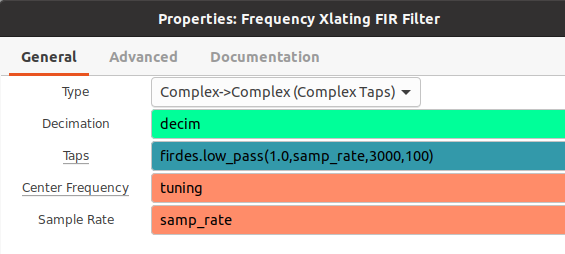
* The Frequency Xlating FIR Filter performs three functions: frequency translation, filtering, and decimation. See [[Frequency_Xlating_FIR_Filter]] for more detail. | |||
[[File:SSB_rcv_FIR_parms.png]] | |||
==== Test receiver section ==== | |||
To test the receiver, generate and run the flowgraph. After a few seconds, a GUI window will open with the Tuning, Fine tuning, and Volume controls, along with the sideband select push buttons. To terminate the process cleanly, click on the 'X' in the upper corner of the GUI rather than using Control-C. | To test the receiver, generate and run the flowgraph. After a few seconds, a GUI window will open with the Tuning, Fine tuning, and Volume controls, along with the sideband select push buttons. To terminate the process cleanly, click on the 'X' in the upper corner of the GUI rather than using Control-C. | ||
| Line 87: | Line 101: | ||
** Click on File -> Save As Use the file name 'SSB_xmt_1'. the extension '.grc' is added automatically | ** Click on File -> Save As Use the file name 'SSB_xmt_1'. the extension '.grc' is added automatically | ||
* The microphone input is defined by an Audio Source block. The parameters are: | * The microphone input is defined by an Audio Source block. The parameters are: | ||
** Sample rate: set to | ** Sample rate: set to 48kHz (use the pull-down) | ||
** Device name: for most microphone jacks built into the computer, the Device name can be left blank; for other cases, see [[Audio_Source#Device_Name]] | ** Device name: for most microphone jacks built into the computer, the Device name can be left blank; for other cases, see [[Audio_Source#Device_Name]] | ||
** OK to block: Yes | ** OK to block: Yes | ||
* For the remainder of the flowgraph, a sample_rate of | * For the remainder of the flowgraph, a sample_rate of 192kHz is used. This value was chosen to give the 16kHz carrier frequency 12 samples per cycle. | ||
* Variable block | * Variable block | ||
** id: samp_rate | ** id: samp_rate | ||
** value: | ** value: 192000 | ||
* To boost the | * To boost the 48kHz sample rate of the audio input to the 192kHz sample rate, a Repeat block with an Interpolation value of 4 is used. | ||
* A QT GUI Range block defines an Audio gain (volume) control | * A QT GUI Range block defines an Audio gain (volume) control | ||
** id: volume | ** id: volume | ||
| Line 104: | Line 118: | ||
* The value of the volume control is used as a multiplier in the Multiply Const block. | * The value of the volume control is used as a multiplier in the Multiply Const block. | ||
** Constant: volume | ** Constant: volume | ||
* The carrier signal (in this example is | * The carrier signal (in this example is 16kHz) is generated by the Signal Source block.<br> | ||
** Sample Rate: samp_rate | ** Sample Rate: samp_rate | ||
** Frequency: carrier_freq | ** Frequency: carrier_freq | ||
| Line 110: | Line 124: | ||
* To create a double sideband signal, the carrier signal is multiplied by the audio signal. | * To create a double sideband signal, the carrier signal is multiplied by the audio signal. | ||
The Band Pass Filter creates the Single Sideband signal by passing the frequencies from | The Band Pass Filter creates the Single Sideband signal by passing the frequencies from 16300Hz to 19000Hz and rejecting the others (the filter method). This gives a signal with only one sideband (upper) and no carrier. The audio frequencies of that signal are 300Hz to 3000Hz. | ||
[[File:SSB_xmt_1_BPF_parms.png]] | |||
* For a real radio transmitter, the output of the Band Pass Filter would be fed to Radio Frequency (RF) hardware. For this tutorial, we are sending the transmit signal to a ZMQ PUSH Sink data socket connected to the receiver section. | * For a real radio transmitter, the output of the Band Pass Filter would be fed to Radio Frequency (RF) hardware. For this tutorial, we are sending the transmit signal to a ZMQ PUSH Sink data socket connected to the receiver section. | ||
| Line 119: | Line 135: | ||
Since a Raspberry Pi has no audio input jack, there are three alternatives: | Since a Raspberry Pi has no audio input jack, there are three alternatives: | ||
# use a USB audio dongle | # use a USB audio dongle and a microphone | ||
# use a USB headset with microphone | # use a USB headset with microphone | ||
# use a USB webcam with microphone | # use a USB webcam with microphone | ||
| Line 139: | Line 155: | ||
* going back to the GRC window, since you just finished building the transmit flowgraph, you can just do a Run. After a few seconds, a GUI window will open with the Audio gain control and the GUI Frequency Sink. | * going back to the GRC window, since you just finished building the transmit flowgraph, you can just do a Run. After a few seconds, a GUI window will open with the Audio gain control and the GUI Frequency Sink. | ||
Speaking into the microphone should show a change in the pattern on the QT GUI Time Sink. The level of modulation can be adjusted with the transmit gain control. You should hear your voice from the speakers. The speaker volume can be adjusted with the receive volume control. Adjust the Fine tuning control until | Speaking into the microphone should show a change in the pattern on the QT GUI Time Sink. The level of modulation can be adjusted with the transmit gain control. You should hear your voice from the speakers. The speaker volume can be adjusted with the receive volume control. Adjust the Fine tuning control until your voice sounds natural to you. Note that very small changes (tens of Hz) will make a difference in how it sounds. Then switch to the lower sideband and hear the results! | ||
To terminate each of the processes cleanly, click on the 'X' in the upper corner of the GUI rather than using Control-C. | To terminate each of the processes cleanly, click on the 'X' in the upper corner of the GUI rather than using Control-C. | ||
== What do | == What to do next == | ||
Now that you have a working system, you can experiment: | Now that you have a working system, you can experiment: | ||
| Line 150: | Line 166: | ||
* make a transmitter using the Weaver method | * make a transmitter using the Weaver method | ||
* make either using the phasing method. hint: use a Hilbert filter for the 90 degree phase shift | * make either using the phasing method. hint: use a Hilbert filter for the 90 degree phase shift | ||
The files used in this simulation are part of a package in https://github.com/duggabe/gr-control If you clone that repository, you will have a complete SSB transceiver which can use either a B200mini or a Pluto SDR. It has been tested with GNU Radio version 3.10.10.0. | |||
Revision as of 21:33, 15 May 2024
This tutorial explains how a Single Sideband (SSB) signal can be generated and received. Rather than using any real hardware for transmission, the signal is sent via a socket from the transmit section to the receive section. The only actual hardware involved is the computer's microphone input and speaker output. In the case of a Raspberry Pi computer, which has no microphone input, three alternatives are presented.
This tutorial can be performed with either GNU Radio (GR) version 3.7 or 3.8 (and later). The Graphical User Interface gnuradio-companion (GRC) is used to create a flowgraph for each section.
Prerequisites
SSB receiver
The Weaver method of SSB demodulation
Traditionally, SSB has been created and received using narrow bandpass filters, or by using a "phasing method" requiring a 90 degree phase shift network across the audio spectrum. In 1956 Donald Weaver published a third method in the Proceedings of the IRE ("A Third Method of Generating and Detecting Single Side Band Signals", Dec. 1956). It involves the use of a local oscillator with a frequency in the middle of the audio spectrum (1500Hz) for the I and Q signals separately, and then adding or subtracting them to recover the upper or lower sideband audio.
Receive from a test file
This section is derived from a tutorial by Dr. Sharlene Katz, California State University, Northridge. See http://www.csun.edu/~skatz/katzpage/sdr_project/sdr/grc_tutorial4.pdf
Download https://www.csun.edu/~skatz/katzpage/sdr_project/sdr/ssb_lsb_256k_complex2.dat.zip and unzip it.
Flowgraph
Using gnuradio-companion (GRC) and the following Block descriptions, build this flowgraph of the receiver test section:
Block descriptions
- The Options block identifies the filename for the flowgraph, a title, author, etc.
- id: SSB_rcv_test
- Click on File -> Save As Use the file name 'SSB_rcv_test'. the extension '.grc' is added automatically
- A Variable block defines the sample rate.
- id: samp_rate
- value: 256000
- Another Variable block defines the decimation factor. Since the Audio Sink (speaker) uses a sample rate of 32kHz, we will reduce (decimate) the incoming sample rate by a factor of 8.
- id: decim
- value: (int)(samp_rate/audio_rate)
- A QT GUI Chooser allows selection of the Upper or Lower sideband
- The value of the Sideband selector is used as a multiplier in the Multiply Const block.
- Constant: reverse
- The Frequency Xlating FIR Filter performs three functions: frequency translation, filtering, and decimation. See Frequency_Xlating_FIR_Filter for more detail.
- A QT GUI Range block defines an Audio gain (volume) control
- id: volume
- default value: 0.2
- start: 0
- stop: 1.0
- step: 0.05
- Widget: choose whatever you like
- The value of the volume control is used as a multiplier in the Multiply Const block.
- Constant: volume
- The speaker output is defined by an Audio Sink block. The parameters are:
- Sample rate: set to 32kHz (use the pull-down)
- Device name: for most speakers (or headphone jacks) built into the computer, the Device name can be left blank; for other cases, see Audio_Sink#Device_Name
- OK to block: Yes
Test receiver
To test the receiver, generate and run the flowgraph. After a few seconds, a GUI window will open with the Tuning, Fine tuning, and Volume controls, along with the sideband select push buttons. You should hear KD7LMO on Lower sideband. To terminate the process cleanly, click on the 'X' in the upper corner of the GUI rather than using Control-C.
Simulation receiver
Flowgraph
Using gnuradio-companion (GRC) and the following Block descriptions, build this flowgraph (a separate one from the test) for the receiver section:
Block descriptions
Note: Several of the parameters are different from the test flowgraph in the previous section.
- The Options block identifies the filename for the flowgraph, a title, author, etc.
- id: SSB_rcv
- Click on File -> Save As Use the file name 'SSB_rcv'. the extension '.grc' is added automatically
- The signal from the transmitter section is received by the ZMQ PULL Source. It is a 16kHz carrier with a sample rate of 192kHz.
- Address: tcp://127.0.0.1:50301
- The Frequency Xlating FIR Filter performs three functions: frequency translation, filtering, and decimation. See Frequency_Xlating_FIR_Filter for more detail.
Test receiver section
To test the receiver, generate and run the flowgraph. After a few seconds, a GUI window will open with the Tuning, Fine tuning, and Volume controls, along with the sideband select push buttons. To terminate the process cleanly, click on the 'X' in the upper corner of the GUI rather than using Control-C.
SSB transmitter
Flowgraph
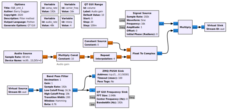
Using gnuradio-companion (GRC) and the following Block descriptions, build this flowgraph (a separate one from the receiver) for the transmitter section:
Block descriptions
- The Options block identifies the filename for the flowgraph, a title, author, etc.
- id: SSB_xmt_1
- Click on File -> Save As Use the file name 'SSB_xmt_1'. the extension '.grc' is added automatically
- The microphone input is defined by an Audio Source block. The parameters are:
- Sample rate: set to 48kHz (use the pull-down)
- Device name: for most microphone jacks built into the computer, the Device name can be left blank; for other cases, see Audio_Source#Device_Name
- OK to block: Yes
- For the remainder of the flowgraph, a sample_rate of 192kHz is used. This value was chosen to give the 16kHz carrier frequency 12 samples per cycle.
- Variable block
- id: samp_rate
- value: 192000
- To boost the 48kHz sample rate of the audio input to the 192kHz sample rate, a Repeat block with an Interpolation value of 4 is used.
- A QT GUI Range block defines an Audio gain (volume) control
- id: volume
- default value: 0.5
- start: 0
- stop: 20.0
- step: 0.1
- Widget: choose whatever you like
- The value of the volume control is used as a multiplier in the Multiply Const block.
- Constant: volume
- The carrier signal (in this example is 16kHz) is generated by the Signal Source block.
- Sample Rate: samp_rate
- Frequency: carrier_freq
- Amplitude: 1.0
- To create a double sideband signal, the carrier signal is multiplied by the audio signal.
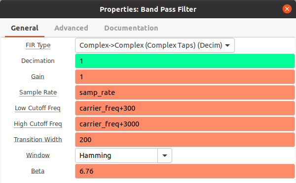
The Band Pass Filter creates the Single Sideband signal by passing the frequencies from 16300Hz to 19000Hz and rejecting the others (the filter method). This gives a signal with only one sideband (upper) and no carrier. The audio frequencies of that signal are 300Hz to 3000Hz.
- For a real radio transmitter, the output of the Band Pass Filter would be fed to Radio Frequency (RF) hardware. For this tutorial, we are sending the transmit signal to a ZMQ PUSH Sink data socket connected to the receiver section.
- Address: tcp://127.0.0.1:50301
Note for Raspberry Pi
Since a Raspberry Pi has no audio input jack, there are three alternatives:
- use a USB audio dongle and a microphone
- use a USB headset with microphone
- use a USB webcam with microphone
Testing
When using GRC, doing a Generate and/or Run creates a Python file with the same name as the .grc file. You can execute the Python file without running GRC again.
For testing this system we will use two processes, so we will need two terminal windows.
Terminal 2:
- Open another terminal window.
- change to whatever directory you used to generate the flowgraph for SSB_rcv
- execute the following command:
python3 -u SSB_rcv.py
- After a few seconds, a GUI window will open with the Tuning, Fine tuning, and Volume controls, along with the sideband select push buttons.
Terminal 1:
- going back to the GRC window, since you just finished building the transmit flowgraph, you can just do a Run. After a few seconds, a GUI window will open with the Audio gain control and the GUI Frequency Sink.
Speaking into the microphone should show a change in the pattern on the QT GUI Time Sink. The level of modulation can be adjusted with the transmit gain control. You should hear your voice from the speakers. The speaker volume can be adjusted with the receive volume control. Adjust the Fine tuning control until your voice sounds natural to you. Note that very small changes (tens of Hz) will make a difference in how it sounds. Then switch to the lower sideband and hear the results!
To terminate each of the processes cleanly, click on the 'X' in the upper corner of the GUI rather than using Control-C.
What to do next
Now that you have a working system, you can experiment:
- make a receiver using the filter method
- make a transmitter using the Weaver method
- make either using the phasing method. hint: use a Hilbert filter for the 90 degree phase shift
The files used in this simulation are part of a package in https://github.com/duggabe/gr-control If you clone that repository, you will have a complete SSB transceiver which can use either a B200mini or a Pluto SDR. It has been tested with GNU Radio version 3.10.10.0.
