Python Block Message Passing: Difference between revisions
| Line 96: | Line 96: | ||
Save the code | Save the code. Notice that errors are listed in the properties of the ''Embedded Python Block'': | ||
[[File:CodeEditorErrorExample.png|500px]] | [[File:CodeEditorErrorExample.png|500px]] | ||
Revision as of 13:58, 11 July 2024
| Beginner Tutorials
Introducing GNU Radio Flowgraph Fundamentals
Creating and Modifying Python Blocks DSP Blocks
SDR Hardware |
This tutorial describes how to read and write messages using the Embedded Python Block.
The previous tutorial, Python Block with Vectors, demonstrates how to write an Embedded Python Block with vector inputs and outputs. The next tutorial, Python Block Tags, describes how to read and write tags in a Python block.
Message Overview
Messages are an asynchronous way to send information between blocks. Messages are good at conveying control data, maintaining a consistent state across blocks and providing some forms of non-data feedback to blocks in a flowgraph.
Messages have a couple of unique properties:
- There is no sample-clock based guarantee when messages will arrive
- Messages are not associated with a specific sample like a tag
- Message input and output ports do not have to be connected in GRC
- Message ports use the Polymorphic Type (PMT)
Message ports are denoted by a grey color and their connections are distinguished by dashed lines:
More information on message passing with PMTs can be found here: Message Passing
Flowgraph Overview
The following flowgraph demonstrates how to:
- Add message sending and receiving ports to Python blocks
- Send messages
- Receive and handle messages
- Adapt block behavior in the work() function based on a received messages
Two custom Embedded Python Blocks are to be created to:
- Select, or multiplex, one of two input signals based on a received message
- Count the number of samples and send a message to the multiplexing block to switch inputs
This tutorial assumes you have already created at least one Embedded Python Block. If not, please complete the tutorial Creating Your First Block before moving on.
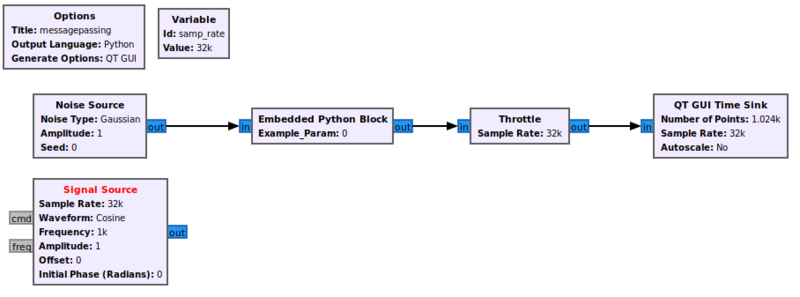
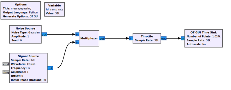
Start by adding the following blocks to the flowgraph and connecting them:
- Noise Source
- Signal Source
- Python Block
- Throttle
- QT GUI Time Sink
Multiplexer: Defining The Block
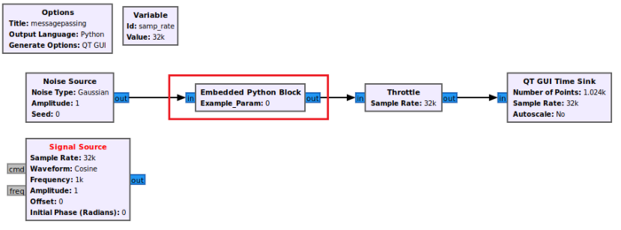
Double-click the Embedded Python Block and open the source in the editor:
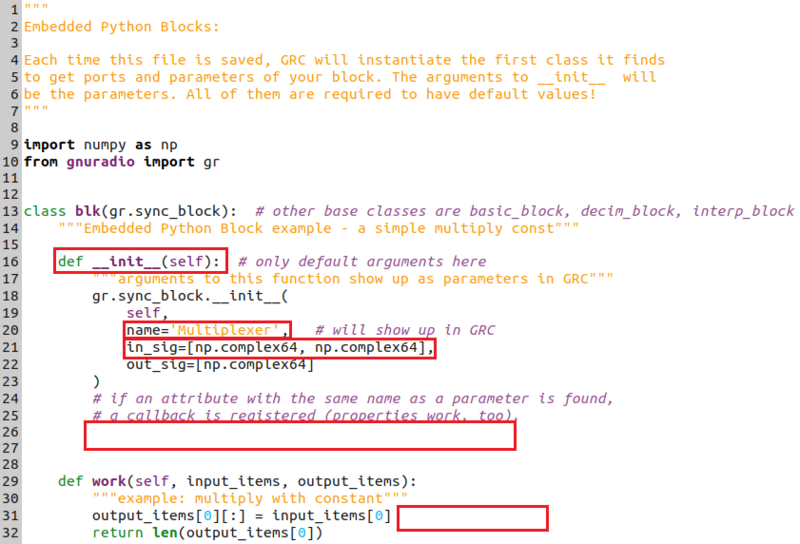
The example_param is not needed, so remove the variable example_param from the signature of the __init__() function:
def __init__(self): # only default arguments here
and delete the line:
self.example_param = example_param
Change the name of the block to Multiplexer:
name='Multiplexer',
Add a second input to the block:
in_sig=[np.complex64, np.complex64],
Delete the multiplication by example_param:
output_items[0][:] = input_items[0]
When all of these changes are made, the code should look as follows:
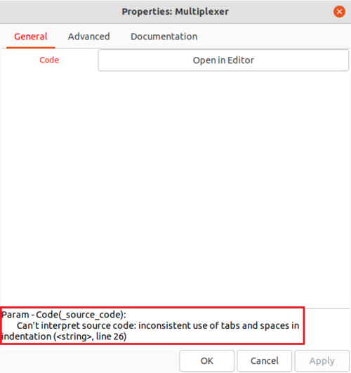
Recall that Python requires the proper indentation. By default, the Embedded Python Block uses indentation of in multiples of 4 spaces. Mixing tabs and spaces raises a syntax error:
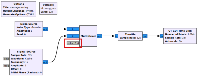
Save the code and return back to GRC. Note how the name of the block has changed and the block now has two inputs. Connect the Noise Source and Signal Source to the two inputs:
Multiplexer: Defining Message Input Port
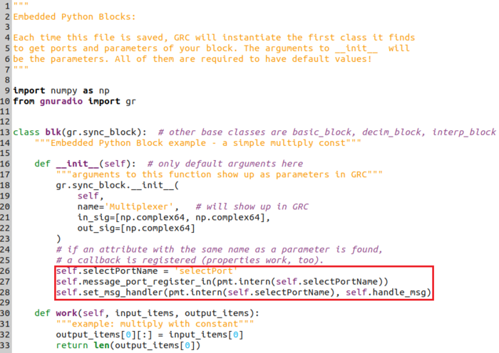
Return to the code editor. An input message port needs to be added. Create a variable to store the message port name:
self.selectPortName = 'selectPort'
Add a line to create, or register, the message input port:
self.message_port_register_in(pmt.intern(self.selectPortName))
Add a line to connect the input port with a message handler.
self.set_msg_handler(pmt.intern(self.selectPortName), self.handle_msg)
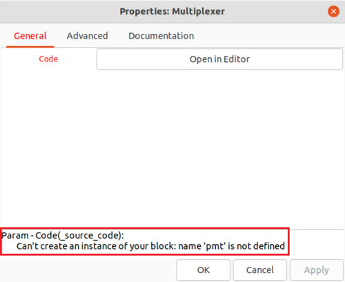
Save the code. Notice that errors are listed in the properties of the Embedded Python Block:
This error says that the pmt library needs to be imported. Return to the code editor and add the proper import statement:
import pmt
Multiplexer: Creating Message Handler
A message handler is the function which is called when a message is received.
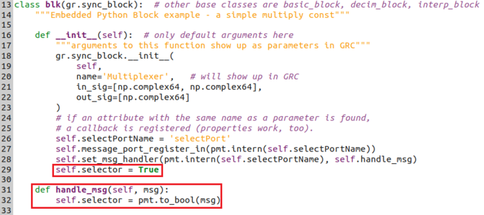
The message handler function has to be defined. This message handler switches between the two input ports based on the received message. The received message is a Boolean that is True or False. Define a new variable under __init__() which is the input selector,
self.selector = True
Define the handle_msg() function:
def handle_msg(self, msg):
    self.selector = pmt.to_bool(msg)
The function pmt.to_bool() takes the message PMT and then converts the data type into Python's Boolean data type. PMTs are used in message passing to abstract data types. For example, messages can be used to send and receive strings, floats, integers and even lists. More information about PMTs can be found on the Polymorphic Types (PMTs) wiki page.
Multiplexer: Using a Message in work()
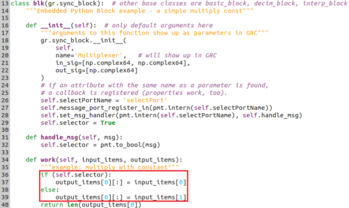
The external interface of the multiplexer is complete. The block's work() function is modified to add the multiplexing operation. Add the following code to the work() function:
if (self.selector):
    output_items[0][:] = input_items[0]
else:
    output_items[0][:] = input_items[1]
The multiplexer block selects port 0 if self.selector = True and port 1 if self.selector = False. The default value of self.selector is defined in the __init__() function.
Save the code (CTRL+S) and return to GRC. The Multiplexer block has a message port selectPort:
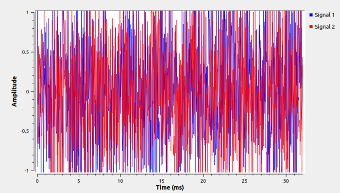
Run the flowgraph to make sure everything is correct before moving on. As mentioned in the introduction, a message port does not have to be connected for a flowgraph to run. Because the default value of self.selector is True, the multiplexer's work() function will select port 0 and send that to the output. The QT GUI Time Sink displays noise:
Selector Control: Defining The Block
Another Embedded Python Block is used to count the number of samples it has received and then send a control message to the multiplexer block in order to toggle the selector.
Start by adding a new Python Block to the flowgraph, in between the Multiplexer and Throttle.
Warning! Drag and drop a NEW Python Block from the block library! Do not copy and paste the existing Multiplexer block, it only creates a second copy of that block.
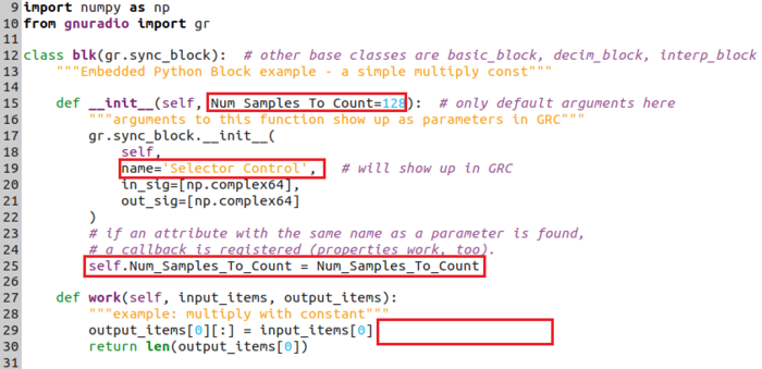
Edit the code for the Embedded Python Block. Change the parameter example_param in the __init__() function:
def __init__(self, Num_Samples_To_Count=128):
Change the name of the block:
name='Selector Control',
Store the Num_Samples_To_Count as a private variable:
self.Num_Samples_To_Count = Num_Samples_To_Count
Remove the example_param multiplication in the work() function:
Selector Control: Defining Message Output Port
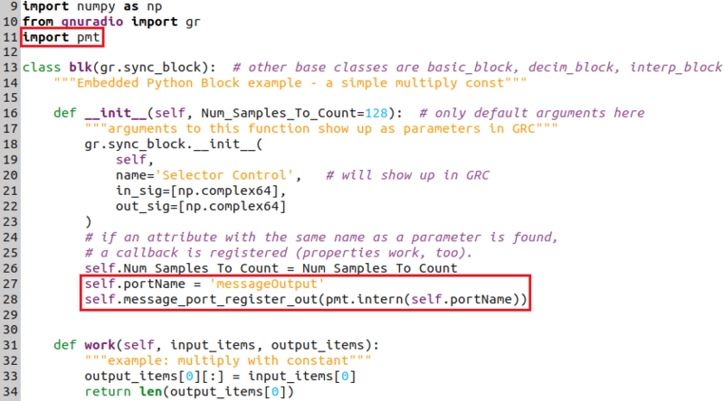
Import the pmt library:
import pmt
Create a variable (self.portName) in the __init__() function containing the name of the output port as a string, messageOutput:
self.portName = 'messageOutput'
A message port is created, or registered, by adding the following line in the __init__()function:
self.message_port_register_out(pmt.intern(self.portName))
Save the code (CTRL + S) and return to GRC. The Selector Control block has a message output port:
Selector Control: Sending a message in work()
A message handler does not need to be defined for an output port. However, the work() function needs to be modified to create the logic for sending messages.
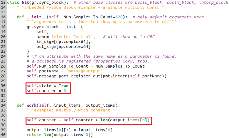
Start by creating two variables in __init__():
self.state = True
self.counter = 0
Add the line to increase the number of counted samples for each call to work():
self.counter = self.counter + len(output_items[0])
Add the logic to send a message once the counter is exceeded:
if (self.counter > self.Num_Samples_To_Count):
    PMT_msg = pmt.from_bool(self.state)
    self.message_port_pub(pmt.intern(self.portName), PMT_msg)
    self.state = not(self.state)
    self.counter = 0
The logic translates the Python Boolean data type of self.state into a PMT using the pmt.from_bool() function call and then sends, or publishes, the message on the output message port. The self.state variable is toggled to its opposite value and the counter is reset.
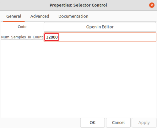
Save the code and return to GRC. Enter 32000 for Num_Samples_To_Count in the properties of the Selector Control block:
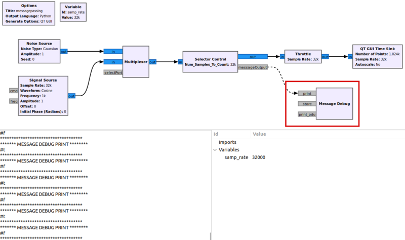
Add the Message Debug block and connect the messageOutput port to it. Running the flowgraph shows the messages are being sent at a rate of once a second, alternating between #t (True) and #f (False):
However, the output message port from Selector Control is not yet connected to the input message port of Multiplexer so the QT GUI Time Sink only shows noise.
Final Flowgraph
Connect the output message port of Selector Control to the input message port of Multiplexer. Notice that the dashed line travels behind the two blocks and can be difficult to see:
Virtual Sinks and Virtual Sources can be used to clean up some of the connections and make the flowgraph easier to understand. Click on the dashed line and delete it. Drag and drop a Virtual Sink and Virtual Source into the workspace. Change the Stream ID to message for both the Virtual Sink and Virtual Source, and then connect them in the flowgraph:
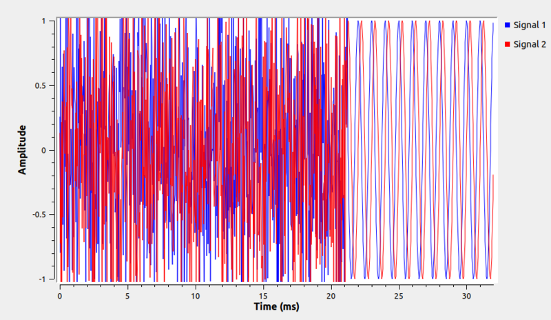
Run the flowgraph. The QT GUI Time Sink shows an alternating output between the Noise Source and Signal Source:
The next tutorial, Python Block Tags, describes how to read and write tags in a Python block.

