RTL-SDR FM Receiver: Difference between revisions
(Created page with "RTL-SDR Based FM Receiver This tutorial describes how to receive broadcast commercial radio stations transmitting Frequency Modulated (FM) signals using the RTL-SDR receiver. The following hardware is needed for this tutorial: * RTL-SDR Receiver * VHF Antenna Please connect the antenna to the RTL-SDR, and plug the RTL-SDR into the USB port on your computer. ==Configuring the RTL-SDR Properties== Add the Soapy RTLSDR Source block to the flowgraph. Soapy [https://gith...") |
Jesternofool (talk | contribs) (Added a link to the "Your First Flowgraph" tutorial for starting GRC, creating a new flowgraph, and saving the file.) |
||
| (56 intermediate revisions by 3 users not shown) | |||
| Line 1: | Line 1: | ||
<div style="float:right"> | |||
{{Template:BeginnerTutorials}} | |||
</div> | |||
This tutorial describes how to receive broadcast commercial radio stations transmitting Frequency Modulated (FM) signals using the RTL-SDR receiver. | This tutorial describes how to receive broadcast commercial radio stations transmitting Frequency Modulated (FM) signals using the RTL-SDR receiver. | ||
The previous tutorial, [[Reading_and_Writing_Binary_Files|Reading and Writing Binary Files]], demonstrates how to read and write radio waveform captures as binary files. The next tutorial, [[B200-B205mini_FM Receiver|B200-B205mini FM Receiver]], describes how to build a broadcast FM receiver using the Ettus Research B200/B205mini receiver. | |||
The following hardware is needed for this tutorial: | |||
* RTL-based SDR (aka "RTL-SDR"); this flowgraph has been tested on the Nooelec NESDR SMArt, the Nooelec Nano Three, the RTL-SDR.com v3, and a generic RTL-SDR with a R820T RF front end. The RTL-SDR.com v4 only works if you've [https://www.rtl-sdr.com/V4/ loaded the v4 drivers]. | |||
* An antenna. As this is tutorial is designed to receive and demodulate FM broadcast signals, which operate in the range of 88 - 108 MHz, a VHF antenna designed to operate in this range is ideal. The number and quality of FM broadcast signals you will be able to receive is related to the how well the antenna operates within that range, as well as the distance between your receive antenna and the FM broadcast towers. | |||
Connect the antenna to the RTL-SDR, and plug the RTL-SDR into the USB port on your computer. | |||
Add the Soapy RTLSDR Source block to the flowgraph. Soapy [https://github.com/pothosware/SoapySDR] is a SDR support library which interfaces with different SDR hardware. | ==RTL-SDR Basic Specifications== | ||
A RTL-SDR is not a single make / model of software defined radio. Several manufacturers make such SDRs, including RTL-SDR Blog and Nooelec, among others. The RTL-SDR is so-called because it is based on [https://www.realtek.com/Product/Index?id=615 the Realtek RTL2832U chip]. This chip provides for analog-to-digital conversion (ADC) and conversion from real to complex samples. Combined with a RF front end chip, such as the Elonics E4000 or the Rafael Micro R802T, R820T2 or R828D, the RTL-SDR provides the capability to capture signals up to roughly 2.5 MHz wide well into the UHF frequency range. | |||
Some standard specifications of RTL-SDRs are: | |||
* Frequency Range: Depends on the specific RF front end chip. The Elonics E4000 specifies a frequency range of 64 - 1700 MHz, but will operate with reduced performance outside of this range. The R820T2 operates from 500 kHz - 1766 MHz. To see the specific RF front end chip, use the "rtl_test" command. | |||
* Digitizer: 8 bits | |||
* Sample Rates: 225 - 300 kHz and 900 kHz - 3.2 MHz. However, typically, sample rates above 2.56 MHz will see dropped samples as the RTL-SDR USB connection is not able to keep pace with sample production. Further, there are some sample rates above 2 MHz which may not be available due to the specific RF front end chip. For example, the Elonics E4000 [https://groups.google.com/g/ultra-cheap-sdr/c/r_BLWQ5C4mw may have issues above 2 MHz]. | |||
* RF Gain Values: Depends on the specific RF front end chip. The Rafael Micro-based chips (R820T, R820T2, R828D) have allowable RF gain values of 0.0, 0.9, 1.4, 2.7, 3.7, 7.7, 8.7, 12.5, 14.4, 15.7, 16.6, 19.7, 20.7, 22.9, 25.4, 28.0, 29.7, 32.8, 33.8, 36.4, 37.2, 38.6, 40.2, 42.1, 43.4, 43.9, 44.5, 48.0, and 49.6 dB. However, if provided a gain value within the upper and lower limits that does not match one of these values, the RTL-SDR will typically select the next allowable lower value. For example, if you attempt to set the gain to 5 dB, the RTL-SDR will set the gain to 3.7 dB (the next allowable lower value). | |||
== Start a New Flowgraph == | |||
For this, you can reference [[Your_First_Flowgraph|the "Your First Flowgraph" tutorial]]. This will step you through starting Gnu Radio Companion for the first time. If you already have opened Gnu Radio Companion and have created flowgraphs, in this case, you can select "File -> New -> QT GUI" (the default selection) to start a new flowgraph. There's also an icon in the upper, left that will do the same thing. Once you've opened this new flowgraph, follow the steps in the "Your First Flowgraph" link to setup the "Options" block and save the file. | |||
==Configure the RTL-SDR== | |||
Add the '''Soapy RTLSDR Source''' block to the flowgraph. Soapy [https://github.com/pothosware/SoapySDR] is a SDR support library which interfaces with different SDR hardware. | |||
[[File:RTL_SDR_FM_add_rtlsdr_block.png]] | |||
The receiver needs to be configured with a proper sampling rate, center frequency and gain value. The RTL-SDR supports multiple sampling rates but in this tutorial the maximum sampling rate of 2.048 MHz is chosen. Update the ''samp_rate'' variable with the value 2048000: | |||
[[File:RTL_SDR_FM_set_samp_rate.png]] | |||
Notice that the sampling rate within the RTL-SDR block has been updated: | |||
[[File:RTL_SDR_FM_rtlsdr_updated_samp_rate.png]] | |||
The RTL-SDR source block still has an undefined ''freq''. The ''freq'' variable needs to be given a frequency associated with a radio station. This tutorial uses the frequency allocations within the United State of America, therefore you will need to modify them according to the allocation for your country. Within the USA, the smallest frequency of a radio station is 87.9 MHz and the largest frequency is 107.9 MHz [https://en.wikipedia.org/wiki/FM_broadcasting_in_the_United_States], and each channel is separated by 200 kHz. | |||
Add two (2) '''QT GUI Range''' blocks into the flowgraph. The properties need to be changed in order to incorporate the frequency allocations for broadcast FM as well as the adjustable gain of the RTL-SDR. | |||
Open the properties of the first '''QT GUI Range''' block and enter the following values: | |||
* ID: freq | |||
* Label: Center Frequency | |||
* Default Value: the frequency of your favorite FM broadcast station. If you don't know, use the start frequency [https://mytuner-radio.com/radio/worldwide-frequencies/ for your country]. For example, [https://mytuner-radio.com/radio/country/rwanda-stations/frequency/fm Rwanda] runs from 87 - 108 MHz. You can use 87e6 for the default value. For this tutorial, we're using 88.5e6. | |||
* Start: Use the start frequency of your country. This tutorial assumes the USA, which starts at 88 MHz. We're going to drop it down a little bit to 87.7e6. | |||
* Stop: 107.9e6 | |||
* Step: Use the step size of your country. We're using 200 kHz (200e3), which is the USA separation. | |||
* GUI Hint: 0,0,1,10 | |||
NOTE: We're going to use the ''GUI Hint'' properties for each of the '''QT GUI Range''' blocks so that they're at the top of the window created when you run the flowgraph. | |||
[[File:QT-GUI-Range-general-properties-freq-annotated.png]] | |||
Open the properties of the second '''QT GUI Range''' block and enter the following values: | |||
* ID: rfGain | |||
* Label: RF Gain (dB) | |||
* Default Value: 10 | |||
* Start: 0 | |||
* Stop: 50 | |||
* Step: 1 | |||
* GUI Hint: 1,0,1,10 | |||
Many RTL-SDRs operate from the Rafael Micro R820T, R820T2 or R828D (RTL-SDR.com v4) RF chip. They use an amplifier that allow for a set of 29 values ranging from 0 - 49.6. The start, stop and step size listed here will get you pretty close to those values without having to enter each of the 29 values as a separate vector. Trust us. This is easier. | |||
[[File:QT-GUI-Range-general-properties-rfGain-annotated.png]] | |||
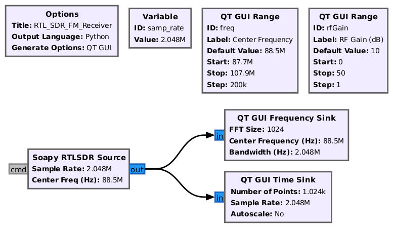
The ''freq'' variable within the '''Soapy RTLSDR Source''' block is now defined. The flowgraph should look like the following: | |||
[[File:RtlsdrFmReceiverSourceOnly.jpg]] | |||
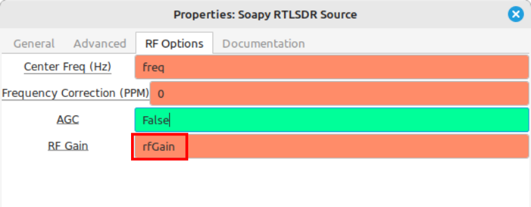
Open the '''Soapy RTLSDR''' Source block properties. Navigate to the ''RF Options'' and enter ''rfGain'' within the ''RF Gain'' window: | |||
[[File:Soapy-RTLSDR-Source-RF-Options-properties-annotated.png]] | |||
==Add Time & Frequency Plots== | |||
Drag in a '''QT GUI Time Sink''' and '''QT GUI Frequency Sink''': | |||
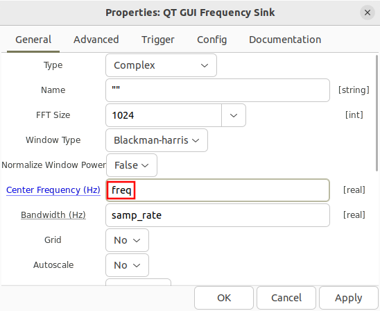
Open the '''QT GUI Frequency Sink''' and enter ''freq'' as the Center Frequency (Hz): | |||
[[File:RTL_SDR_FM_freq_sink_center_freq.png]] | |||
Connect the '''QT GUI Time Sink''' and '''QT GUI Frequency Sink''' blocks: | |||
[[File:RtlsdrFmReceiverNoDemod.jpg]] | |||
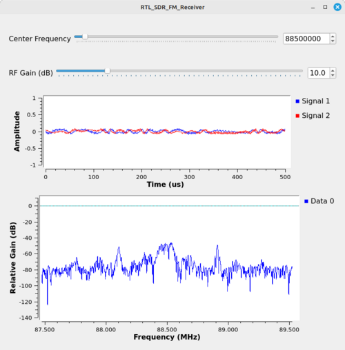
Run the flowgraph. A time plot and frequency plot will be displayed. This simple flowgraph represents a basic tuner application, such that dragging the slider bar or entering a frequency manually will retune the RTL-SDR and start producing sampled data. | |||
[[File:RTL-SDR-FM-Receiver-10-gain.png|500px]] | |||
Due to the nature of the RTL-SDR and how it presents data to Gnu Radio, a '''QT GUI Time Sink''' at the output of the RTL-SDR source block gives an indication of signal strength and potential overload. The image above, with the ''RF Gain'' set to 10, shows the data in the time sink as relatively low amplitude. Depending on the antenna connected to your specific RTL-SDR, your time domain may be higher or lower amplitude. Further, your spectral display (the '''QT GUI Frequency Sink''') will also appear differently. | |||
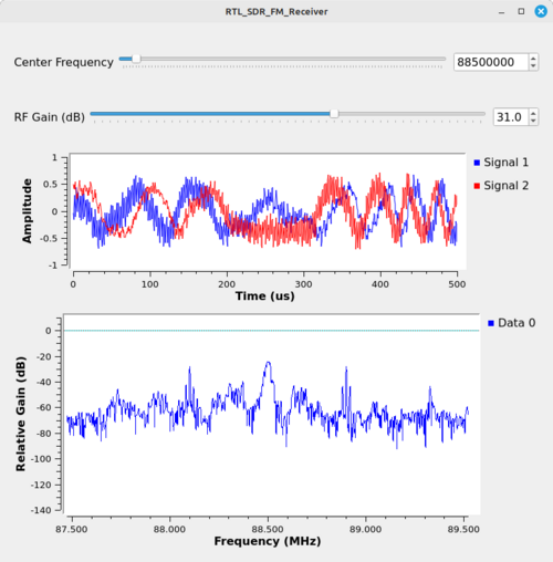
Adjusting the ''RF Gain'' value higher adds gain to the RF front end of the RTL-SDR. This will boost the signal strength and increase the signal-to-noise ratio (SNR). For example, increasing the gain to 31 dB will increase the amplitude within the time sink, as shown below: | |||
[[File:RTL-SDR-FM-Receiver-31-gain.png|500px]] | |||
Increasing the gain to where the amplitudes within the time sink are close to, but not surpassing, the top and bottom of the display (with limits set to +/-1, which is the default) is optimal for proper reception. | |||
==FM Demodulator== | |||
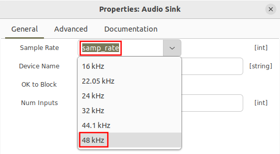
An '''Audio Sink''' block is needed to play the sound of a demodulated FM radio station. Drag in an '''Audio Sink''' block and open the properties. Notice there are a couple choices for sampling rates to choose from. Select '''48 kHz''': | |||
[[File:RTL_SDR_FM_audio_sink_properties.png]] | |||
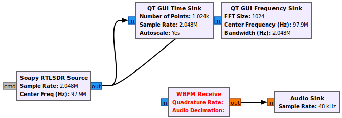
The flowgraph should now look like the following: | |||
[[File:RTL_SDR_FM_flowgraph_with_audio_sink.png]] | |||
The question is how to get from the output of the RTL-SDR which is complex IQ sampled at 2.048 MHz to the input of the '''Audio Sink''' block which requires real samples at a sampling rate of 48 kHz? The rest of this tutorial will work backwards from the '''Audio Sink''' and establishing blocks and connections towards the output of the RTL-SDR. | |||
The next block that is needed is the an FM demodulator. Drag in the '''WBFM Receive''' block, which takes complex IQ as an input, demodulates the FM thereby producing real output samples and also performs a decimation. | |||
[[File:RTL_SDR_FM_add_wbfm_receive.png]] | |||
Recall from earlier in the tutorial that FM broadcast channels allocated 200 kHz, therefore we want to process as much of that bandwidth as possible with the FM demodulator. The '''WBFM Receive''' block can perform a decimation from a larger input sampling rate to the required '''Audio Sink''' input of 48 kHz. The decimation factor must be an integer, and 4*48 kHz = 192 kHz which is close to the total bandwidth of the frequency allocation. | |||
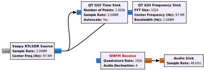
Add a '''WBFM Receive''' block, open the properties and enter in the quadrature rate of 192 kHz and an audio decimation of 4. Note that the quadrature rate must be evenly divisible by the audio decimation factor, and that the audio decimation must be an integer. | |||
[[File:RTL_SDR_FM_wbfm_receive_properties.png]] | |||
The flowgraph should now look like the following: | |||
[[File:RTL_SDR_FM_flowgraph_with_WBFM.png]] | |||
A sample rate change is needed to convert from the RTL-SDR output of 2.048 MHz to the WBFM input of 192 kHz. The required sampling rate change can be simplified as 192000/2048000 = 192/2048 = 3/32, a rational ratio. Therefore the '''Rational Resampler''' block can be used to implement the sample rate change. | |||
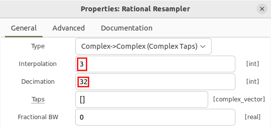
Drag in the '''Rational Resampler''' block and open the properties. Enter 3 for the interpolation and 32 for the decimation: | |||
[[File:RTL_SDR_FM_rational_resampler_properties.png]] | |||
The flowgraph is now complete and should look like the following. | |||
[[File:RTL-SDR-FM-Receiver-original.jpg|800px]] | |||
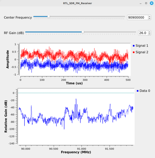
Run the flowgraph. The same GUI window that was displayed previously will appear but now audio should be playing through your computer. You can drag the bar at the top of the screen to tune to different channels. | |||
[[File:RTL-SDR-FM-Receiver-90M9CF.png|500px]] | |||
==Diagnosing Overrun Problems== | |||
When you run your flowgraph if you get a string of “aUaUaU” and the audio comes in and out periodically then you have probably entered a sample rate wrong somewhere along the way. Double check all of the sample rate values and interpolation and decimation rate changes. | |||
[[File:RTL_SDR_FM_sample_rate_overflows.png]] | |||
== Additional Feature - Volume Control == | |||
An additional you can add to this flowgraph is a volume control. Volume is controlled by the amplitude of the signal going into the [[Audio Sink]]. We'll add another [[QT GUI Range]] block as well as a [[Multiply Const]] block to adjust the volume. Place the '''Multiply Const''' block between the '''WBFM Receive''' and '''Audio Sink''' blocks. Your flowgraph should be similar to this: | |||
[[File:RTL-SDR-FM-Receiver-with-volume-control.jpg|800px]] | |||
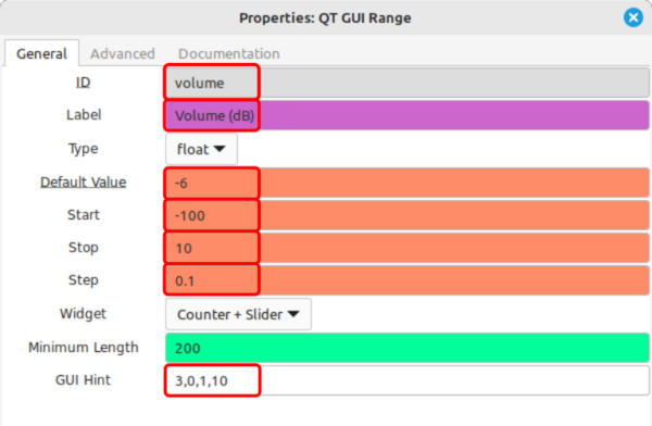
Open the properties for the just-added '''QT GUI Range''' block and enter the following values: | |||
* ID: volume | |||
* Label: Volume (dB) | |||
* Default Value: -6 | |||
* Start: -100 | |||
* Stop: 10 | |||
* Step: 0.1 | |||
* GUI Hint: 3,0,1,10 | |||
[[File:RTL-SDR-FM-Receiver-volume-range-properties-annotated.png|600px]] | |||
Open the properties of the '''Multiply Const''' block and enter the following values: | |||
* IO Type: float | |||
* Constant: 10**(volume/20) | |||
[[File:RTL-SDR-FM-Receiver-Multiply-Const-properties-annotated.png]] | |||
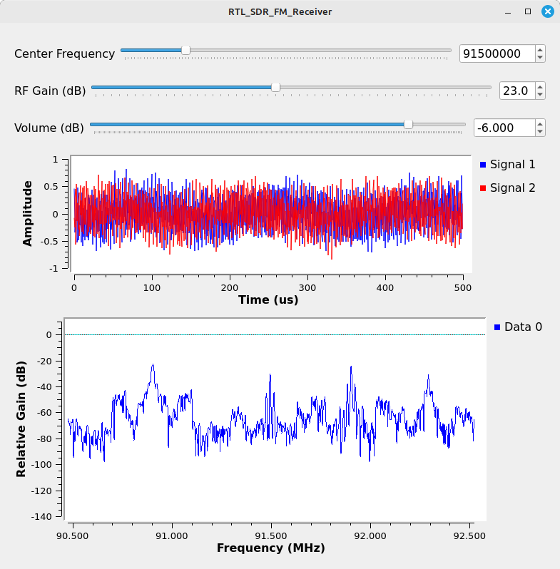
Run the flowgraph. Now the display will have a slider for the audio volume, as shown below. Using decibel (dB, a logarithmic scale) values as opposed to linear values (e.g. 0 - 100, for example) means that the audio adjustments will more closely follow human hearing, which is also logarithmic. Values less than 0 will lower the volume, while values greater than 0 will raise the volume. A value of 0 will be no change in the amplitude. NOTE: Amplitudes greater than 1 or less than -1 going into an '''Audio Sink''' block will typically cause audio distortion. | |||
[[File:RTL-SDR-FM-Receiver-display-with-volume-control.png]] | |||
== Stereo Version flowgraph == | |||
A stereo version flowgraph file can be found in [[Media:RTL_SDR_rcv.grc]]. | |||
== Next Tutorial - Ettus Research B200/B205mini Receiver == | |||
The next tutorial, [[B200-B205mini_FM Receiver|B200-B205mini FM Receiver]], describes how to build a broadcast FM receiver using the Ettus Research B200/B205mini receiver. | |||
Latest revision as of 01:58, 7 October 2025
| Beginner Tutorials
Introducing GNU Radio Flowgraph Fundamentals
Creating and Modifying Python Blocks DSP Blocks
SDR Hardware |
This tutorial describes how to receive broadcast commercial radio stations transmitting Frequency Modulated (FM) signals using the RTL-SDR receiver.
The previous tutorial, Reading and Writing Binary Files, demonstrates how to read and write radio waveform captures as binary files. The next tutorial, B200-B205mini FM Receiver, describes how to build a broadcast FM receiver using the Ettus Research B200/B205mini receiver.
The following hardware is needed for this tutorial:
- RTL-based SDR (aka "RTL-SDR"); this flowgraph has been tested on the Nooelec NESDR SMArt, the Nooelec Nano Three, the RTL-SDR.com v3, and a generic RTL-SDR with a R820T RF front end. The RTL-SDR.com v4 only works if you've loaded the v4 drivers.
- An antenna. As this is tutorial is designed to receive and demodulate FM broadcast signals, which operate in the range of 88 - 108 MHz, a VHF antenna designed to operate in this range is ideal. The number and quality of FM broadcast signals you will be able to receive is related to the how well the antenna operates within that range, as well as the distance between your receive antenna and the FM broadcast towers.
Connect the antenna to the RTL-SDR, and plug the RTL-SDR into the USB port on your computer.
RTL-SDR Basic Specifications
A RTL-SDR is not a single make / model of software defined radio. Several manufacturers make such SDRs, including RTL-SDR Blog and Nooelec, among others. The RTL-SDR is so-called because it is based on the Realtek RTL2832U chip. This chip provides for analog-to-digital conversion (ADC) and conversion from real to complex samples. Combined with a RF front end chip, such as the Elonics E4000 or the Rafael Micro R802T, R820T2 or R828D, the RTL-SDR provides the capability to capture signals up to roughly 2.5 MHz wide well into the UHF frequency range.
Some standard specifications of RTL-SDRs are:
- Frequency Range: Depends on the specific RF front end chip. The Elonics E4000 specifies a frequency range of 64 - 1700 MHz, but will operate with reduced performance outside of this range. The R820T2 operates from 500 kHz - 1766 MHz. To see the specific RF front end chip, use the "rtl_test" command.
- Digitizer: 8 bits
- Sample Rates: 225 - 300 kHz and 900 kHz - 3.2 MHz. However, typically, sample rates above 2.56 MHz will see dropped samples as the RTL-SDR USB connection is not able to keep pace with sample production. Further, there are some sample rates above 2 MHz which may not be available due to the specific RF front end chip. For example, the Elonics E4000 may have issues above 2 MHz.
- RF Gain Values: Depends on the specific RF front end chip. The Rafael Micro-based chips (R820T, R820T2, R828D) have allowable RF gain values of 0.0, 0.9, 1.4, 2.7, 3.7, 7.7, 8.7, 12.5, 14.4, 15.7, 16.6, 19.7, 20.7, 22.9, 25.4, 28.0, 29.7, 32.8, 33.8, 36.4, 37.2, 38.6, 40.2, 42.1, 43.4, 43.9, 44.5, 48.0, and 49.6 dB. However, if provided a gain value within the upper and lower limits that does not match one of these values, the RTL-SDR will typically select the next allowable lower value. For example, if you attempt to set the gain to 5 dB, the RTL-SDR will set the gain to 3.7 dB (the next allowable lower value).
Start a New Flowgraph
For this, you can reference the "Your First Flowgraph" tutorial. This will step you through starting Gnu Radio Companion for the first time. If you already have opened Gnu Radio Companion and have created flowgraphs, in this case, you can select "File -> New -> QT GUI" (the default selection) to start a new flowgraph. There's also an icon in the upper, left that will do the same thing. Once you've opened this new flowgraph, follow the steps in the "Your First Flowgraph" link to setup the "Options" block and save the file.
Configure the RTL-SDR
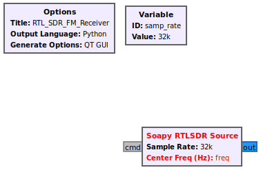
Add the Soapy RTLSDR Source block to the flowgraph. Soapy [1] is a SDR support library which interfaces with different SDR hardware.
The receiver needs to be configured with a proper sampling rate, center frequency and gain value. The RTL-SDR supports multiple sampling rates but in this tutorial the maximum sampling rate of 2.048 MHz is chosen. Update the samp_rate variable with the value 2048000:
Notice that the sampling rate within the RTL-SDR block has been updated:
The RTL-SDR source block still has an undefined freq. The freq variable needs to be given a frequency associated with a radio station. This tutorial uses the frequency allocations within the United State of America, therefore you will need to modify them according to the allocation for your country. Within the USA, the smallest frequency of a radio station is 87.9 MHz and the largest frequency is 107.9 MHz [2], and each channel is separated by 200 kHz.
Add two (2) QT GUI Range blocks into the flowgraph. The properties need to be changed in order to incorporate the frequency allocations for broadcast FM as well as the adjustable gain of the RTL-SDR.
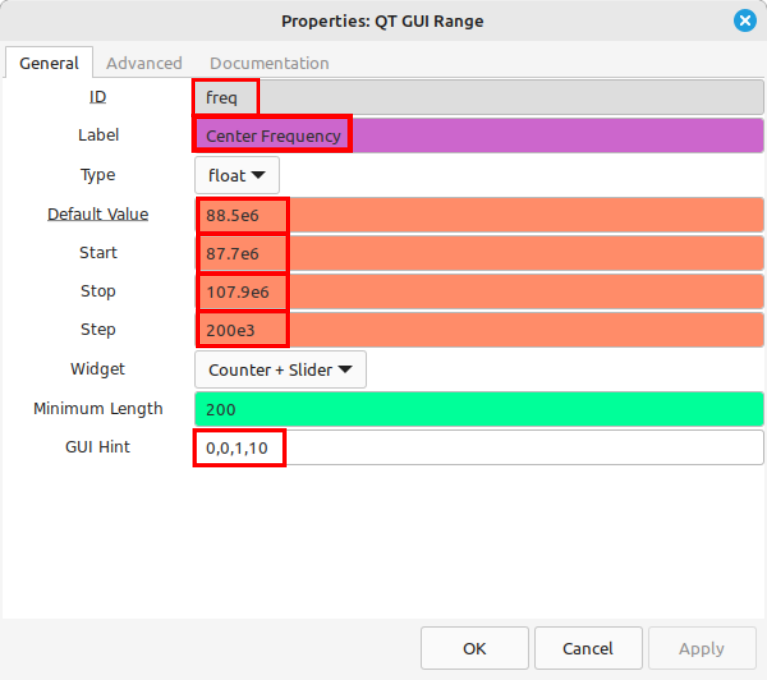
Open the properties of the first QT GUI Range block and enter the following values:
- ID: freq
- Label: Center Frequency
- Default Value: the frequency of your favorite FM broadcast station. If you don't know, use the start frequency for your country. For example, Rwanda runs from 87 - 108 MHz. You can use 87e6 for the default value. For this tutorial, we're using 88.5e6.
- Start: Use the start frequency of your country. This tutorial assumes the USA, which starts at 88 MHz. We're going to drop it down a little bit to 87.7e6.
- Stop: 107.9e6
- Step: Use the step size of your country. We're using 200 kHz (200e3), which is the USA separation.
- GUI Hint: 0,0,1,10
NOTE: We're going to use the GUI Hint properties for each of the QT GUI Range blocks so that they're at the top of the window created when you run the flowgraph.
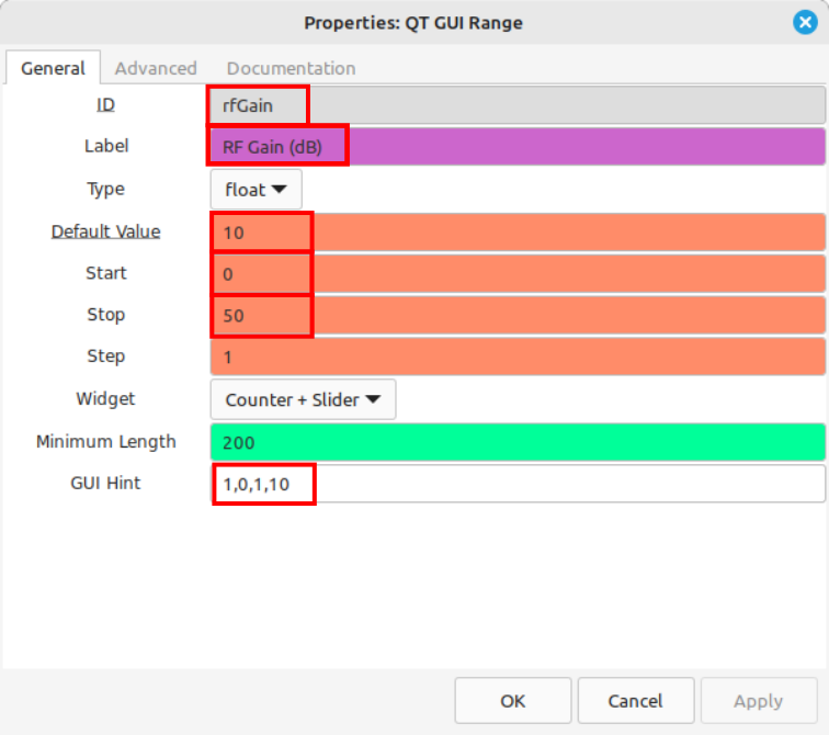
Open the properties of the second QT GUI Range block and enter the following values:
- ID: rfGain
- Label: RF Gain (dB)
- Default Value: 10
- Start: 0
- Stop: 50
- Step: 1
- GUI Hint: 1,0,1,10
Many RTL-SDRs operate from the Rafael Micro R820T, R820T2 or R828D (RTL-SDR.com v4) RF chip. They use an amplifier that allow for a set of 29 values ranging from 0 - 49.6. The start, stop and step size listed here will get you pretty close to those values without having to enter each of the 29 values as a separate vector. Trust us. This is easier.
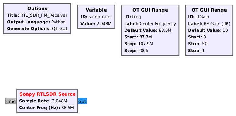
The freq variable within the Soapy RTLSDR Source block is now defined. The flowgraph should look like the following:
Open the Soapy RTLSDR Source block properties. Navigate to the RF Options and enter rfGain within the RF Gain window:
Add Time & Frequency Plots
Drag in a QT GUI Time Sink and QT GUI Frequency Sink:
Open the QT GUI Frequency Sink and enter freq as the Center Frequency (Hz):
Connect the QT GUI Time Sink and QT GUI Frequency Sink blocks:
Run the flowgraph. A time plot and frequency plot will be displayed. This simple flowgraph represents a basic tuner application, such that dragging the slider bar or entering a frequency manually will retune the RTL-SDR and start producing sampled data.
Due to the nature of the RTL-SDR and how it presents data to Gnu Radio, a QT GUI Time Sink at the output of the RTL-SDR source block gives an indication of signal strength and potential overload. The image above, with the RF Gain set to 10, shows the data in the time sink as relatively low amplitude. Depending on the antenna connected to your specific RTL-SDR, your time domain may be higher or lower amplitude. Further, your spectral display (the QT GUI Frequency Sink) will also appear differently.
Adjusting the RF Gain value higher adds gain to the RF front end of the RTL-SDR. This will boost the signal strength and increase the signal-to-noise ratio (SNR). For example, increasing the gain to 31 dB will increase the amplitude within the time sink, as shown below:
Increasing the gain to where the amplitudes within the time sink are close to, but not surpassing, the top and bottom of the display (with limits set to +/-1, which is the default) is optimal for proper reception.
FM Demodulator
An Audio Sink block is needed to play the sound of a demodulated FM radio station. Drag in an Audio Sink block and open the properties. Notice there are a couple choices for sampling rates to choose from. Select 48 kHz:
The flowgraph should now look like the following:
The question is how to get from the output of the RTL-SDR which is complex IQ sampled at 2.048 MHz to the input of the Audio Sink block which requires real samples at a sampling rate of 48 kHz? The rest of this tutorial will work backwards from the Audio Sink and establishing blocks and connections towards the output of the RTL-SDR.
The next block that is needed is the an FM demodulator. Drag in the WBFM Receive block, which takes complex IQ as an input, demodulates the FM thereby producing real output samples and also performs a decimation.
Recall from earlier in the tutorial that FM broadcast channels allocated 200 kHz, therefore we want to process as much of that bandwidth as possible with the FM demodulator. The WBFM Receive block can perform a decimation from a larger input sampling rate to the required Audio Sink input of 48 kHz. The decimation factor must be an integer, and 4*48 kHz = 192 kHz which is close to the total bandwidth of the frequency allocation.
Add a WBFM Receive block, open the properties and enter in the quadrature rate of 192 kHz and an audio decimation of 4. Note that the quadrature rate must be evenly divisible by the audio decimation factor, and that the audio decimation must be an integer.
The flowgraph should now look like the following:
A sample rate change is needed to convert from the RTL-SDR output of 2.048 MHz to the WBFM input of 192 kHz. The required sampling rate change can be simplified as 192000/2048000 = 192/2048 = 3/32, a rational ratio. Therefore the Rational Resampler block can be used to implement the sample rate change.
Drag in the Rational Resampler block and open the properties. Enter 3 for the interpolation and 32 for the decimation:
The flowgraph is now complete and should look like the following.
Run the flowgraph. The same GUI window that was displayed previously will appear but now audio should be playing through your computer. You can drag the bar at the top of the screen to tune to different channels.
Diagnosing Overrun Problems
When you run your flowgraph if you get a string of “aUaUaU” and the audio comes in and out periodically then you have probably entered a sample rate wrong somewhere along the way. Double check all of the sample rate values and interpolation and decimation rate changes.
Additional Feature - Volume Control
An additional you can add to this flowgraph is a volume control. Volume is controlled by the amplitude of the signal going into the Audio Sink. We'll add another QT GUI Range block as well as a Multiply Const block to adjust the volume. Place the Multiply Const block between the WBFM Receive and Audio Sink blocks. Your flowgraph should be similar to this:
Open the properties for the just-added QT GUI Range block and enter the following values:
- ID: volume
- Label: Volume (dB)
- Default Value: -6
- Start: -100
- Stop: 10
- Step: 0.1
- GUI Hint: 3,0,1,10
Open the properties of the Multiply Const block and enter the following values:
- IO Type: float
- Constant: 10**(volume/20)
Run the flowgraph. Now the display will have a slider for the audio volume, as shown below. Using decibel (dB, a logarithmic scale) values as opposed to linear values (e.g. 0 - 100, for example) means that the audio adjustments will more closely follow human hearing, which is also logarithmic. Values less than 0 will lower the volume, while values greater than 0 will raise the volume. A value of 0 will be no change in the amplitude. NOTE: Amplitudes greater than 1 or less than -1 going into an Audio Sink block will typically cause audio distortion.
Stereo Version flowgraph
A stereo version flowgraph file can be found in Media:RTL_SDR_rcv.grc.
Next Tutorial - Ettus Research B200/B205mini Receiver
The next tutorial, B200-B205mini FM Receiver, describes how to build a broadcast FM receiver using the Ettus Research B200/B205mini receiver.
